
philf
1 kW
So...
We've all seen it mentioned in various places throughout the forum. The latest versions of the Cycle Analyst firmware support it. And even without it, attempts have been made to gather empirical data from the operation of an e-bike just the same.
Yup. We're talking about logging.
When Justin started out on his Cross-Canada trek, he'd intended to continuously collect data from his rig (all the time it was operating) for future analysis. The telemetry system was nothing more than a laptop computer connected to his Cycle Analyst via a serial connection - but before he got too far into his trip, the laptop failed and there were electrical issues with the way the power supply was hooked up, to boot.
The idea, at least, was interesting to me - though the rudimentary data you can get from the CA's view of the world seemed a bit incomplete for doing anything more than comparative work. Observing consumption figures without knowing what the terrain was like, for example (are we going uphill?), would only tell us that we're using "more" - without indicating "how come".
Whatever one does with the data, the point is that a moving e-bike is no place for a full-fledged personal computer. Its bulk notwithstanding, the energy requirements make it impractical. I'd wondered if some handheld device, like an iPAQ or something, might somehow be made to work - but this still seemed inappropriate (or expensive). Commercially available purpose-built data loggers exist, but these get REALLY expensive for anything that gives you an ability to customize what it does.
Being the kind of guy who likes to play with microcontrollers, I'd wondered if some simpler solution might be cobbled together. Something that could take the incoming serial data and stash it on some form of memory device for later upload to a PC. I quickly learned that reading and writing from a variety of memory devices was no problem - but, if one wanted to do it "conveniently", one had to go through a few hoops. As an example, it's not that hard to build something that would write raw data to an SD memory card - but, if one wanted to put the data on the card in a fashion that was meaningful to a PC (i.e. - using some form of known file system), the coding overhead became quite huge, as did the memory requirement of the microcontroller utilized.
Then, while looking for something else entirely, I stumbled across GHI Electronics and one of their particularly interesting products. http://www.ghielectronics.com/product/1. The uALFAT ("Micro AL FAT") is actually just an NXP (Philips) microcontroller into which they have toasted firmware with a very specific purpose - to allow simple devices to perform operations on files stored in the FAT16 or FAT32 file system (with long filenames!) through a high-level interface, thus alleviating the need for the host application to understand ANY kind of file system at all!
I had to have one.
So, looking at the available options, I went for one of their "modules" that contains the uALFAT chip, as well as an SD card socket. Communications with the core of the thing is through a handful of pins brought out on a 16 pin header. The device understands regular serial (you can actually talk directly to it through a regular serial port - albeit, at TTL levels - using nothing more than Hyperterminal), as well as SPI and I2C. I was hooked!
Grabbing the microcontroller of choice (yup, the Microchip PIC16F690 of which I have too many), I quickly breadboarded a system to talk to the uALFAT. Having just ONE serial input wasn't enough, though. I had originally envisioned up to FOUR serial inputs - streaming data to four different files concurrently from different sources (with tagging to help line the data up after the fact), and the PIC only has a single port on it. So, I settled on using an exteral dual UART that would give me two serial ports in addition to the one built-in, and which used the same SPI or I2C interface to address it as the uALFAT - thus eliminating a lot of un-necessary interfacing complexity (this adds complexity to the firmware one must write to control the things, though).
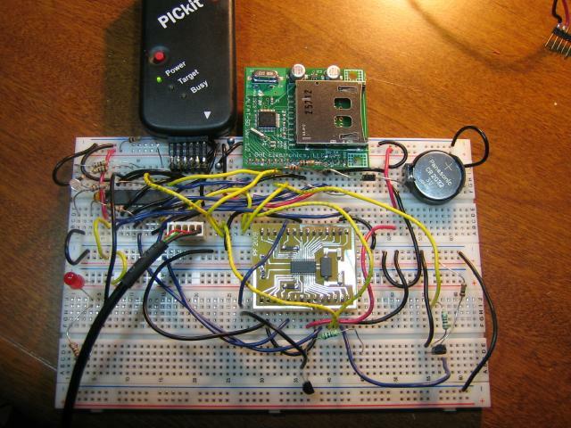
After some hacking about, THIS took shape:
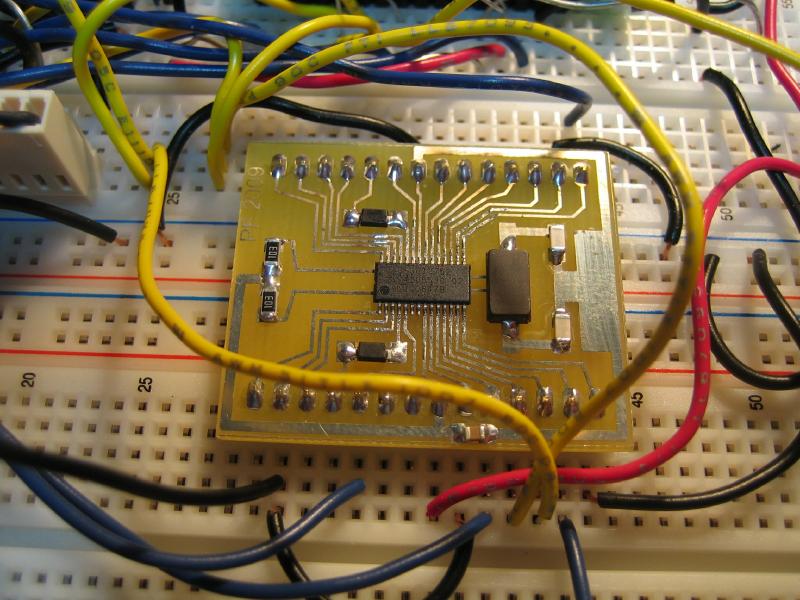
One of the problems one runs into with most modern chips is that they only come in packages which are suitable for surface mounting, so to work with the dual UART of choice, I had to make an "adaptor" board. The extra components are the crystal circuit for the baud rate generator, and a couple of discretes that are used to interface to the inbound 5V serial signals - this thing is a 3.3V part....
After some fooling about, I quickly had a "proof of concept" that clearly showed me that this was feasible. So, with some further "hardware doodling", and a desire to make this thing fit into a package that was as small as possible, I drew up the final circuit in Eagle and mapped a printed circuit board for the thing. The added "flying" components pictured on the breadboard, above, have to do with some differences in the interfacing requirements of the uALFAT versus the UART if they are to share the same communications bus (I used SPI to simplify the software somewhat), and to permit a particular non-standard signal I was anticipating to be passed in as readily as the signal from the CA. More on that later.
The resulting proto-board...
It's actually two sided, with about twenty manual "througplates" required to get it working. Once populated the, the uALFAT module plugs in to a header and piggybacks on top of the whole affair. The result fits in a package about the size of a deck of cards. I had originally intended to have jacks on the back of the case for the inputs, but even these required more real estate than I had, so wound up being "dangling" connectors. I used mouse/keyboard connectors for these.
You'll notice a bunch of loose wirewrap wires on there... After fully populating the board, I made the horrible discovery that I'd flipped the header when doing the PCB layout. The circuit would work, if the uALFAT was mounted backwards, but this was obviously no good - I cut the traces on the 8, or so, signals that needed to be reworked and wired them back u correctly by hand. The revision has already been made to the PCB layout for the NEXT time. Doh. Hey. I *did* label the board as version 0.1a") .
.
So, with everything together, and the proof-of-concept code still running, the device does this... It watches the two serial ports (I reserved the third, on-board one, for debugging/monitoring during development), and if it sees incoming data on either of them it opens a file on the SD card and starts streaming the data to that file. Each port creates its own file, and (assuming that the incoming data is plaintext with a carriage return after each line), I've added a "serializer" field to the data that allows the two files to be merged into one representation of real-time events.
What's on the second port that required a little bit of additional circuitry?
One of these...
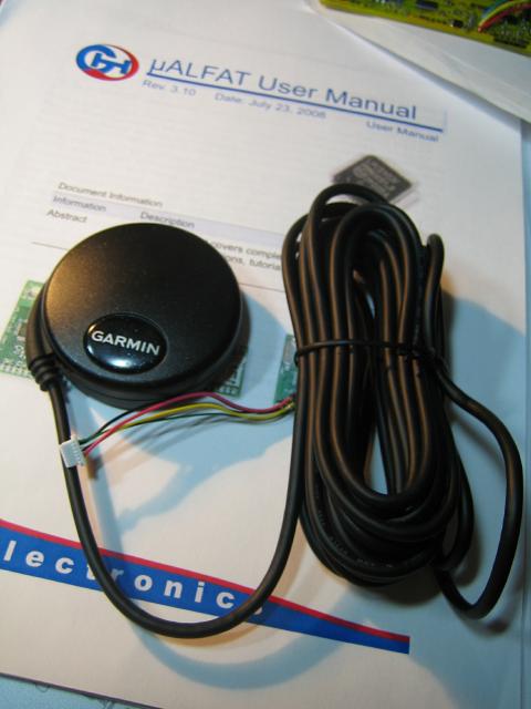
This GPS Puck from Garmin is an OEM device that, once powered, continually streams data (NMEA format) about where you are, how fast you're going, elevation, how your fix was calculated and by how many satellites, etc., etc.. It's damned sensitive. I can get a fix IN MY BASEMENT with this thing! I've set it up to give me output every second, to match the CA - the data stream from the puck includes the real time (VERY accurate), too, which is something else that nicely augments the data from the CA.
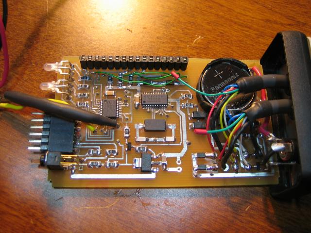
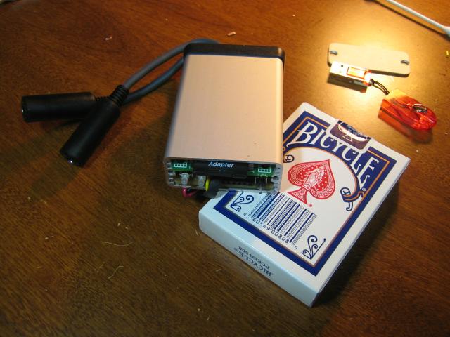
The whole thing wound up quite tidy - couldn't resist using the "Bicycle" card deck as a size reference..
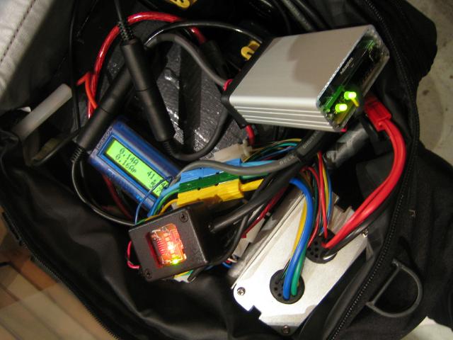
I can't put the cover on the front with my diagnostic connector hanging out, but that didn't stop me from going for a run with it... There's a long way to go on the firmware (and some software to massage the raw log data), but I thought I'd share all this as I've had a few conversations about this with others on the forum, in private, and there does some to be some interest in projects like this...
We've all seen it mentioned in various places throughout the forum. The latest versions of the Cycle Analyst firmware support it. And even without it, attempts have been made to gather empirical data from the operation of an e-bike just the same.
Yup. We're talking about logging.
When Justin started out on his Cross-Canada trek, he'd intended to continuously collect data from his rig (all the time it was operating) for future analysis. The telemetry system was nothing more than a laptop computer connected to his Cycle Analyst via a serial connection - but before he got too far into his trip, the laptop failed and there were electrical issues with the way the power supply was hooked up, to boot.
The idea, at least, was interesting to me - though the rudimentary data you can get from the CA's view of the world seemed a bit incomplete for doing anything more than comparative work. Observing consumption figures without knowing what the terrain was like, for example (are we going uphill?), would only tell us that we're using "more" - without indicating "how come".
Whatever one does with the data, the point is that a moving e-bike is no place for a full-fledged personal computer. Its bulk notwithstanding, the energy requirements make it impractical. I'd wondered if some handheld device, like an iPAQ or something, might somehow be made to work - but this still seemed inappropriate (or expensive). Commercially available purpose-built data loggers exist, but these get REALLY expensive for anything that gives you an ability to customize what it does.
Being the kind of guy who likes to play with microcontrollers, I'd wondered if some simpler solution might be cobbled together. Something that could take the incoming serial data and stash it on some form of memory device for later upload to a PC. I quickly learned that reading and writing from a variety of memory devices was no problem - but, if one wanted to do it "conveniently", one had to go through a few hoops. As an example, it's not that hard to build something that would write raw data to an SD memory card - but, if one wanted to put the data on the card in a fashion that was meaningful to a PC (i.e. - using some form of known file system), the coding overhead became quite huge, as did the memory requirement of the microcontroller utilized.
Then, while looking for something else entirely, I stumbled across GHI Electronics and one of their particularly interesting products. http://www.ghielectronics.com/product/1. The uALFAT ("Micro AL FAT") is actually just an NXP (Philips) microcontroller into which they have toasted firmware with a very specific purpose - to allow simple devices to perform operations on files stored in the FAT16 or FAT32 file system (with long filenames!) through a high-level interface, thus alleviating the need for the host application to understand ANY kind of file system at all!
I had to have one.
So, looking at the available options, I went for one of their "modules" that contains the uALFAT chip, as well as an SD card socket. Communications with the core of the thing is through a handful of pins brought out on a 16 pin header. The device understands regular serial (you can actually talk directly to it through a regular serial port - albeit, at TTL levels - using nothing more than Hyperterminal), as well as SPI and I2C. I was hooked!
Grabbing the microcontroller of choice (yup, the Microchip PIC16F690 of which I have too many), I quickly breadboarded a system to talk to the uALFAT. Having just ONE serial input wasn't enough, though. I had originally envisioned up to FOUR serial inputs - streaming data to four different files concurrently from different sources (with tagging to help line the data up after the fact), and the PIC only has a single port on it. So, I settled on using an exteral dual UART that would give me two serial ports in addition to the one built-in, and which used the same SPI or I2C interface to address it as the uALFAT - thus eliminating a lot of un-necessary interfacing complexity (this adds complexity to the firmware one must write to control the things, though).
After some hacking about, THIS took shape:
One of the problems one runs into with most modern chips is that they only come in packages which are suitable for surface mounting, so to work with the dual UART of choice, I had to make an "adaptor" board. The extra components are the crystal circuit for the baud rate generator, and a couple of discretes that are used to interface to the inbound 5V serial signals - this thing is a 3.3V part....
After some fooling about, I quickly had a "proof of concept" that clearly showed me that this was feasible. So, with some further "hardware doodling", and a desire to make this thing fit into a package that was as small as possible, I drew up the final circuit in Eagle and mapped a printed circuit board for the thing. The added "flying" components pictured on the breadboard, above, have to do with some differences in the interfacing requirements of the uALFAT versus the UART if they are to share the same communications bus (I used SPI to simplify the software somewhat), and to permit a particular non-standard signal I was anticipating to be passed in as readily as the signal from the CA. More on that later.
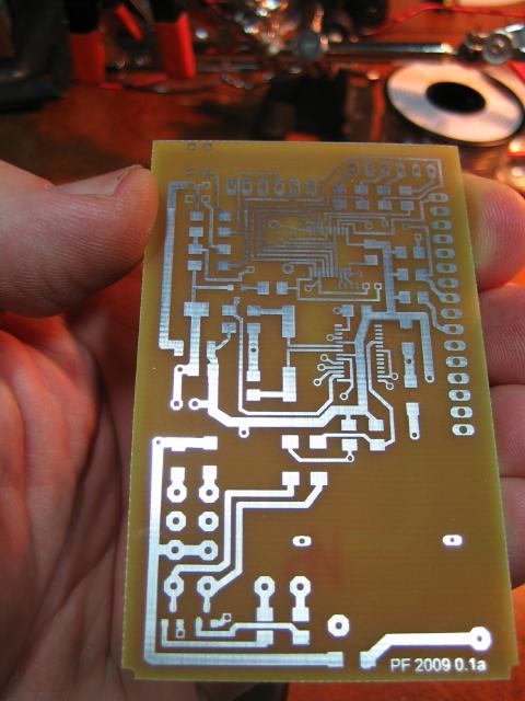
The resulting proto-board...
It's actually two sided, with about twenty manual "througplates" required to get it working. Once populated the, the uALFAT module plugs in to a header and piggybacks on top of the whole affair. The result fits in a package about the size of a deck of cards. I had originally intended to have jacks on the back of the case for the inputs, but even these required more real estate than I had, so wound up being "dangling" connectors. I used mouse/keyboard connectors for these.
You'll notice a bunch of loose wirewrap wires on there... After fully populating the board, I made the horrible discovery that I'd flipped the header when doing the PCB layout. The circuit would work, if the uALFAT was mounted backwards, but this was obviously no good - I cut the traces on the 8, or so, signals that needed to be reworked and wired them back u correctly by hand. The revision has already been made to the PCB layout for the NEXT time. Doh. Hey. I *did* label the board as version 0.1a
.So, with everything together, and the proof-of-concept code still running, the device does this... It watches the two serial ports (I reserved the third, on-board one, for debugging/monitoring during development), and if it sees incoming data on either of them it opens a file on the SD card and starts streaming the data to that file. Each port creates its own file, and (assuming that the incoming data is plaintext with a carriage return after each line), I've added a "serializer" field to the data that allows the two files to be merged into one representation of real-time events.
What's on the second port that required a little bit of additional circuitry?
One of these...
This GPS Puck from Garmin is an OEM device that, once powered, continually streams data (NMEA format) about where you are, how fast you're going, elevation, how your fix was calculated and by how many satellites, etc., etc.. It's damned sensitive. I can get a fix IN MY BASEMENT with this thing! I've set it up to give me output every second, to match the CA - the data stream from the puck includes the real time (VERY accurate), too, which is something else that nicely augments the data from the CA.
The whole thing wound up quite tidy - couldn't resist using the "Bicycle" card deck as a size reference..
I can't put the cover on the front with my diagnostic connector hanging out, but that didn't stop me from going for a run with it... There's a long way to go on the firmware (and some software to massage the raw log data), but I thought I'd share all this as I've had a few conversations about this with others on the forum, in private, and there does some to be some interest in projects like this...