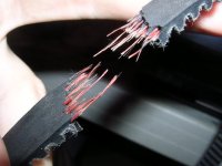
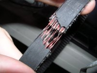
My belt broke - motor's timing pulley isn't secure

swbluto

10 TW
Joined
May 30, 2008
Messages
9,430
DSCN5876.JPG

DSCN5875.JPG

This a 500-5m (I think it's 15mm wide) belt that was "Made in Japan" and originally meant for a 200 watt scooter. I was probably pushing 1200 watts through at the time it broke and it broke accelerating full throttle from a dead stop. Now, I'm not sure why it broke. About 1/3-1/4 of the belt was hanging off the wheel's timing pulley (Sprocket like thing that's meant for belts - just a heads up because I didn't know what a timing pulley was until about 6-7 months ago) since it wasn't completely aligned and the belt was under moderate tension.

Do you think there's an upgrade I could make that'd make it nearly indestructible? I can't really increase size dimensions much since the timing pulley is built into the wheel and I'm working with a tightly fitted space to begin with. Do they make "Kevlar" or some other material type of belt that's clearly superior to this one?

Also, on a possibly related note, the motor's shaft doesn't tightly fit against the timing pulley attached to it, so I found out that it "bounces" up and down by a little bit as it rotates which is the source of this irritable clicking I've been getting and it's probably been the cause of past clicking. Is there some sort of fix for that? Like maybe a "filler" material that can make the shaft held securely against the timing pulley's inner walls?

Thanks everyone! You all have been really helpful in that past with your extremely valuable insight and experience.
 
That's very similar to the belt I run on my Zappy. Belt alignment is very critical. Pulley diameter is also important. If the pulley is too small, the bending radius of the belt is too tight and causes the internal fibers to break over time.
I use a Goodyear aramid (kevlar-like) belt and have over 400 miles on it with over 1kw of motor.

A belt tensioner might be useful, but the two pulleys must be perfectly in the same plane and parallel.

As far as filler goes, JB weld is popular. You could also try very thin brass shim stock or feeler gauge material. Even blue Loctite is good if you wait long enough for it to harden.
 
Ahhh, shucks. I thought a belt was much more flexible with timing pulley / belt alignment than a chain. To align it, I think I would have to make the motor's shaft longer so I could attach the timing pulley backwards (the motor didn't really come with a long shaft), and to make the shaft longer would probably mean replacing it with a longer one. I think it'd have to be a custom shaft (Since I don't see anyone selling 8mm motor shafts online) which means I'd have to machine a rod and... that seems to involve resources I don't have. But, if anyone could help....

Where could one get a bare rod from which to machine a shaft? In particular, an 8mm rod?
How would one go about to cut the groove the circlip would fit into? Does that require a lathe? What kind of common resource would have a lathe available? Are there small, light cheap lathes available to buy?

And I have access to a grinder, so I think I could machine the flats that would secure the shaft. But... I don't know about a "press" or what I've heard called an "arbor press" to press the shaft in and out of the motor's bell.

Also, how would one cut a screw hole into the timing pulley so that would could use two set screws on the motor's shaft? (The timing pulley has only one set-screw hole for a single set screw)

On a pretty good note, fixing the alignment would surely make busting the bearing on the wheel a little harder.
 
swbluto said:
Ahhh, shucks. I thought a belt was much more flexible with timing pulley / belt alignment than a chain.
No, as fechter said, it's much more critical than for chain.

Loctite 638 (or equivalent) is good for securing loose pulleys.

Can't you move the motor? Lengthening the shaft will put more strain on the motor bearings...
 
Use a timing belt from a car motor.... they are nearly indestructible.
 
My 15mm wide belt on my recumbent is good for 7kw.

Alignment is an issue, so is tension.

From your pics, I can see the belt teeth are leaning in one direction. That indicates the belt was skipping before it broke.

#1 Alignment.
#2 Proper tension.
#3 A minimum of 14 tooth motor pulley to get proper belt wrap.

Matt
 
Okay, so what kind of tension is proper? I was trying to make the tension so that I could manually take the belt off if the scooter breaks down so that I could use it as a normal kick scooter without the motor's cogging, but yet nearly as tight as it could go without violating the above condition.

And, it's possible to move the motor back a few mm using washers on the motor's mounting onto the motor mount or from the motor mount to the frame, but then things are very close together and the motor's spinning at 3000 rpm... (During bumpy terrain, probably closer to 2000 rpm)

And lengthening the shaft to reverse the timing pulley would actually put the belt closer to the main motor bearing, although the set screw part would be further away... I'm not exactly sure where the force is transmitted, but for now, it seems it's the set screw but if some loctite or similar glue is put in there, then maybe the majority of the force would be transmitted where I decide to apply the glue?
 
swbluto said:
And lengthening the shaft to reverse the timing pulley would actually put the belt closer to the main motor bearing, although the set screw part would be further away...

Ah ok. That's fine. I didn't read your post with enough attention. :)
 
Miles said:
swbluto said:
And lengthening the shaft to reverse the timing pulley would actually put the belt closer to the main motor bearing, although the set screw part would be further away...

Ah ok. That's fine. I didn't read your post with enough attention. :)

Haha, I wish. It was most likely due to me not really explaining it completely with all possible details since, well, that would've made one long boring post. :wink: But I can highlight details where they seem pertinent afterwards. A picture would be more communicatively efficient, but unfortunately the belt broke, so I really can't show it in it's entirety. But, maybe, just maybe....

Anyways, I'm still not sure where the force is transmitted. I noticed on the original huge motor, the motor's timing pulley was backwards with the set screw towards the end of the shaft which made the belt closer to the motor, so maybe that's actually the "correct" orientation?
 
swbluto said:
Anyways, I'm still not sure where the force is transmitted. I noticed on the original huge motor, the motor's timing pulley was backwards with the set screw towards the end of the shaft which made the belt closer to the motor, so maybe that's actually the "correct" orientation?

Yes, you want the belt as close to the bearings as possible.
 
Here are some pictures for reference. The wheel is slightly angled away so the belt would stay on the wheel's timing pulley. Also, I tried to get the firt picture where the wheel's timing pulley is as parallel as possible to the camera's line of sight so the size of the misalignment could be discerned.

DSCN5877.JPG

DSCN5878.JPG

DSCN5881.JPG

DSCN5880.JPG

DSCN5879.JPG
 
An alternative would be to drill/tap 2 new holes for grub screws through the troughs of the motor pulley teeth. Then you wouldn't need to lengthen the shaft (the pulley hub would be redundant).
 
Hmmmm, I'm looking at the picture and I was thinking... maybe that black metal tube on the right of the wheel's axle could be replaced with something slightly shorter so the wheel could be shifted rightwards? Oh, but the shaft has a bare spot there, so I think that effect could be limited(There's a nut on the inside to the right of the tube and I reasoned its function is to prevent the metal tube from coming into contact with the frame).

Also, when I fit the wheel into the frame, it had to stretch it by 1/2" or so. I don't know how it was originally built and I'm not even sure I have all of the original pieces, and so there's a few washers on the axle to give what I thought was "proper spacing" but maybe it isn't proper.
 
Miles said:
An alternative would be to drill/tap 2 new holes for grub screws through the troughs of the teeth.

I'm not sure how much depth there is from the trough to the center of the pulley, but it doesn't seem like a lot and to tap a single trough seems like it'd require tiny set screws and would that upto the forces of securing the motor's pulley?

If all checks out, I may investigate the black magick of tapping.
 
There must be more depth than in the hub of the pulley, yes? You don't necessarily need to keep the grub screw diameter within the trough.... 3mm dia. screw should be fine.
 
Miles said:
There must be more depth than in the hub of the pulley, yes? You don't necessarily need to keep the grub screw diameter within the trough....

So, the epicenter of the blast site is in the trough, but the fallout area may include the adjacent crests? I like your thinking. :mrgreen:

And, I'm starting to question my understanding of what a "pulley's hub" is. Is it the round smooth area the original set screw was or is it some kind of special "inner cylinder" that's along the entire length of the shaft-way? Or something else?
 
swbluto said:
So, the epicenter of the blast site is in the trough, but the fallout area may include the adjacent crests? I like your thinking. :mrgreen:
LOL!

And, I'm starting to question my understanding of what a "pulley's hub" is. Is it the round smooth area the original set screw was or is it some kind of special "inner cylinder" that's along the entire length of the shaft-way? Or something else?
The smooth area where the set screw is. Usually the hub is smaller in diameter than the circle of the troughs of the teeth are. ....
 
Okay, well, I'm not really worried about any misunderstandings because it seems there's about 4 mm of depth of the pulley's shaft-way and the trough of teeth, so it seems like it should be plenty. Here's a pic for a better idea of what this pulley looks like.

DSCN5884.JPG

Just to make sure I do this right... I have to...

1) drill a hole slightly less than the set screw?
2) Insert the tap screw; put the bar around it and twist
3) When fully penetrated, it's finished?

Also, should set-screw be such that the top of the set-screw is at or below the trough's original surface? That way, the belt won't touch the set screw, methinks.

Also, I got this die and tap set because I don't have one. Does anyone think it'll work?

http://www.harborfreight.com/cpi/ctaf/displayitem.taf?Itemnumber=39424

I have no idea what those circles with the three holes are for.

So, the ideal configuration is two set screws set on two flats on the shaft, them being angled 90 degrees relative to each other. Would it be wise to make these two flat areas right next to each other or on different lengths of the shaft?
 
Yikes! I didn't realise it would have so few teeth.... If the depth is more than the diameter, you should be ok. You can always use Loctite on the threads and the shaft.

Yes, the screw needs to be completely below the surface.

You'll need a tap to match your grub screw diameter and pitch. It looks to be 3/16" or 4mm size? The smallest in the set you linked to is 1/4".

You need to look up the exact tapping drill size.

It's best to back off the tap by half a turn after every cutting turn.

The "circles with the three holes" are "dies", for cutting male threads :)

What shape is the end of your grub screw?
 
Unfortunately, it'll never work....j/k

You may also want to buy a drill set to go with the tap set.
The tap should tell you what drill size to use.

i.e. 4-40 set screw requires a #43 drill.

http://www.korit.com/tapndrill.htm

HF has an inexpensive drill set that has #drills, fractional sizes and letter sizes.

So, it's just like you said. Drill a smaller hole (use the chart) in a valley.
Then match up the tap to the set screw, say 4-40.
Use a little oil on the tap when you start to tap the hole. Keep everything nice
and perpendicular to the hole, and start twisting. And you'll have a tapped hole before you know it.
Put two flats 90 degrees opposed from each other.

That pulley definitely looks "wollered" out. You may want to get a new one and ream it to 8mm according to your shaft size.
That means you may have to buy an 8mm reamer. Stock drive products has pulleys with a 6mm bore in that size.
Do you know if its a GT pulley/belt or HTD pulley/belt?
A reamer will make a really nice 8mm hole, whereas an 8mm drill leaves an OK hole.
 
You could also probably "screw" the set screw and just pin the pulley to the shaft.

Look for roll pins.. They are super easy. You just drill a hole in the pulley and the shaft
(pulley is mounted on shaft). Tap the roll pin into place. Done.
 
I was just planning on buying new set screws since I have to anyways, and I didn't think the screw I have would be best although it might be the best size (it's metric and metric is more expensive in the US). What would the best shape be? The current one is like a dip in the the center with a round ridge towards the outside - it looks like the shaft's hole molded to that shape so now there's an "inverted dip"/mound in the middle which the set screw covers.

Anyways, I looked at the set and it made mention of those weird sizes 4, 8, 10, 12, etc. and according to some guide online, it seemed the smallest corresponded to 3/32" which is nearly 1/16" so I think it should cover the appropriate range.
 
Well, the problem is that the solid black area where the set screw used to go (What I think has been referred to as a hub) doesn't intercept the shaft when the pulley is reversed, which I apparently need to reverse. Do you think a roll pin idea would work if were tapped somewhere in the trough of the teeth? It seems roll pins look weaker than set screws since they appear hollow and mounting on the teeth would seem to increase the leverage and thus the forces the roll pin would endure, but I would so much more appreciate that than dealing with set screws and flats. Also, I might be able to get it done sooner since I already have an ordinary drill set to do the drilling but I'm not sure if it'll work with this type of metal as I imagine it's hardened?

Oh, it's an HTD pulley.

And, "wollered" out. haha... ok, so I take it that means worn out.
 
Back
Top