My first ebike - Schwinn Foldable AL1020

The7

10 kW
Joined
Jul 11, 2007
Messages
761
Location
Vancouver
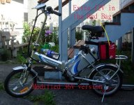
This is my first new foldable ebike Schwinn AL1020 bought from CT.
The ebike has an 6061 aluminum and weights 40 lbs without battery pack.
The 24V 12Ah SLA battery pack weights about 20 lbs.
The total is 60 lbs.


A digital speedometer was installed on the RHS of the handle bar next to the throttle.
The magnet and the speed sensor were at the rear wheel.

The hub motor is a brushless motor with an internal fixed gear.
It is quite free to pedal without battery.

I am confident that the motor should be able to stand 36V with no problem.
Only thing to be concerned is the controller.

From no-load test on 24V supply, the max speed is 30km/h.
What will be the max speed on flat?
I think that it should be about 24 km/h by taking 80% of that of no-load. (To be verified ).


I road tested my ebike on flat by riding both direction on the same road with full throttle and non-pedalling.
The max speed towards North was 27 km/h and towards South was 25 km/h.
Thus the average on flat is approximatly 26 km/h which is about 85% of the no-load speed.
So my prediction is quite close.

In my opinion, 25 km/h is a bit too low. I would like if it could be 30-35 km/h on flat and it is difficult assist to pedal if the speed is above 20 km/h because it has a single-speed pedalling.

If the 36V supply could be used,
then the max speed would be 45 km/h at no-load and 36km/h on flat.

That is why I try to find an way improve it.
36 V battery supply would be the suitable soluttion if the stock controller could stand.
 
No-load test results on AL1020

A)Using 24 V 12 Ah SLA Battery

1) Quiescent Current = 0.06A

2) Max Throttle
Max No-load Speed = 30.7 km/h
Current = 1.22 A
Then input power = 24X1.22 = 29.3 W

B) Using 36 V supply ( 24V 12Ah + 12V 14Ah)
3) Quiescent Current = 0.07 A

4) Max Throttle
Max No-load Speed = 45.7 km/h
Current = 1.60A
Then input power = 36X1.60= 57.6 W

5) Partial Throttle at Speed = 30.7 km/h
Current = 0.95A
Then input power = 36X0.95= 34.2 W

Comments:
1) The 24V stock controller was used for both 24V and 36V test.
2) Quiesent current is only increased slightly from 0.06 to 0.07A.
3) Max no-load speed is approximately proportional to the battery voltage.
4) For the same speed, current for 36V battery is lower. But the input power in higher. This means the heating of the FET would not be a problem.
5) It seems that the stock controller could work at 36V. The 3 big capacitors are rated at 100V 100uF while the voltage ratings of the FETs are unknown because they are potted inside the casing.
 
The tire size of AL1020 is 16"X1.75".
The measured circumference 124cm.
Hence the actual diameter is only 15.5".

This measured circumference is used to set the Raleigh digital speedometer.

Then for this tire:
Speed => Wheel rpm
20 km/h => 269 rpm
30 km/h => 403 rpm
40 km/h => 538 rpm

The hub motor is brushless with internal gear and free-wheel.
I guess that its gear ratio is about 4 to 7.
So the rpm of this motor is much higher (say 4 to 7 times the wheel rpm).


Theoretically the physical size of an motor is inversely proportional to the gear ratio for the same power.
Some "nano" hub motors use gears with a gear ratio greater than 10. But the motor rpm will be very high and may not be long-lasting.
 
The7 said:
5) It seems that the stock controller could work at 36V. The 3 big capacitors are rated at 100V 100uF while the voltage ratings of the FETs are unknown because they are potted inside the casing.

Most likely FETs have at least a 55v rating. Some controllers use a 78xx voltage regulator, which are rated for 35v max. The regulator in most controllers is fed by a separate wire from the on/off switch or keyswitch, not straight off the main battery wires. If you're worried about the regulator, you can cut the supply side of the on/off switch and re-route it to a tap on the battery pack (24v). This preserves the low voltage cutout function as well (if it has one). It would result in a slight imbalance on the pack, since the idle current (.06A) would be drawn from only part of the pack.

Most controllers I've dissected have a transistor/zener voltage regulator for the first stage, and they can usually take as much as the FETs.

Any idea what the maximum current (limit) is? It might be more than your meter is made to take.
 
fechter said:
Most likely FETs have at least a 55v rating. Some controllers use a 78xx voltage regulator, which are rated for 35v max. The regulator in most controllers is fed by a separate wire from the on/off switch or keyswitch, not straight off the main battery wires. If you're worried about the regulator, you can cut the supply side of the on/off switch and re-route it to a tap on the battery pack (24v). This preserves the low voltage cutout function as well (if it has one). It would result in a slight imbalance on the pack, since the idle current (.06A) would be drawn from only part of the pack.

Most controllers I've dissected have a transistor/zener voltage regulator for the first stage, and they can usually take as much as the FETs.

Any idea what the maximum current (limit) is? It might be more than your meter is made to take.

This is inside of the controller.
The circuit board is potted with transparent expoxy.
The 3 big cap clearly show 100V 100uF.
The 6 FET are screwed on inside of the casing.

There is an "regulator look" IC at the right-hand top corner.
It seems a yellow wire is used in place of a resistor connecting the battery supply to this regulator IC for this "24V" model !??

Data on the controller:
Ananda Drive Technologies Co Lld of Shanghai, China
Model No: 2415DLC-11Z0 / N12C
Date of Manu: 2006-11-29

Model No 2415 may mean 24V 15A controller.
There is only one power switch on the battery pack and there is no dedicated key switch for the controller.
 
I've never seen that model before.

Epoxy is great for keeping rain out, but a pain when you want to modify something.

Perhaps inserting a resistor in the yellow wire would drop the input to the regulator. If you measured the input to the regulator, you could find a resistor that keeps it around 24v.

A 36v SLA battery might be near 45v at peak during charging. If the regulator is rated for 35v input, it could become unhappy.

Disconnecting the batteries from the controller during charging would help.
 
fechter said:
I've never seen that model before.

Epoxy is great for keeping rain out, but a pain when you want to modify something.

Agreed. My hands are partly tied

fechter said:
Perhaps inserting a resistor in the yellow wire would drop the input to the regulator. If you measured the input to the regulator, you could find a resistor that keeps it around 24v.

May try to do later.
To drop 60 mA for 12V, it needs a R of 200 ohm.

fechter said:
A 36v SLA battery might be near 45v at peak during charging. If the regulator is rated for 35v input, it could become unhappy.

Disconnecting the batteries from the controller during charging would help.
No problem because the same socket is used for either charging or connecting to the controller (But not at the same time).

I think that this controller has an LVC. When an 12V is used, the Empty LED lights up and the motor will not turn at all with any throttle.
 
Road test this morning ( Thursday 2007/07/26)

Place: Vancouver BC
Temp = 19 deg C
Weather = Excellent

A) 24 V battery
1)Max speed at flat = 25 km/h
Current = 6A to 9A
2) Slight Slope speed = 19 km/h
Current = 13 to 14 A
3) Max current is limitd by controller to 14.8A
Then max input power = 24X14.8= 355 W

B) 36 V battery
1) Max speed at flat = 35 km/h
2) Slight Slope speed = 25 km/h
3 Max current is also limited by controller to 14.8A
Then max input power is limited to 36X 14.8 = 532 W
5) The testing time = 75 min
6) Average Speed about 19.8 km/h
7) Distance travelled = 25km
8) The 36 battery are all "EMPTY" with 11.93 V, 11.99V and 12.0V at the end of the road test.
9) Pedalling was only used to assist starting and could not be used at all if the speed was over 20 km/h.
10) Both controller and hub motor were only luke-warm.


Comments:
1) The ride using 36V was much enjoyable.
2) There was no heat problem for controller and motor.
3) Higher speed and torque.
4) If the stock controller does fail, wll ungrade it to 36V 20A one.
5) Will take the risk to use the 36 V version from now on
 
That's great news! When is the 48v test? 8)
35km/h is just right on the flats, and is about the speed I pedal my mountain bikes at comfortably.
 
Lowell said:
That's great news! When is the 48v test? 8)
35km/h is just right on the flats, and is about the speed I pedal my mountain bikes at comfortably.

Ha! Ha!
Any reliable and economical 36/48V 20A controller available??
 
A Crystalyte 72v/20a would do the job nicely. In stock at http://www.ebikes.ca.

http://en.wikipedia.org/wiki/Avalanche_breakdown

If you have access to a current limited power supply, it would be easy to safely test how the controller likes 48v.
 
My new 36V version.
The extra 12V battery is inside the red bag.
 

Attachments

  • DSCN7186 copy.jpg
    DSCN7186 copy.jpg
    66.8 KB · Views: 8,524
This morning . I took my ebike to downtown Vancouver, touring around English Bay and Stanley Park. The whole trip recorded 43 km.

On most roads, I could manage 30-38 km/h.
Pedalling is only used to assist starting. Pedalling could not be used if the speed is over 20 km/h due to one pedalling speed.

On gentle slopes about 25 km/h. If I had multiple gears I would pedal assist to 30 km/h for this gentle slope and also save battery energy.

On difficult slopes about 20km/h with pedal assisting. I don't think that I could pedal only on these slopes.

Around English Bay and scene routes 15km/h mainly by pedalling. Bicycle-style ebikes on these routes will be definitely more friendly than Vespa-style ebike.

On the way back for the last several kms, I could only do 20 km/h or less because the batteries were EMPTY.
Voltages for the stock 24 V 12Ah battery: 12.03V and 12.03V (EMPTY).
Voltage for the added 12V 14 Ah battery: 11.68V (too weak).
It seems the 14Ah has less Ah than the stock 12 Ah.

Comments:
1) There were no heat problem in both controller and motor when working at 36V battery. Both controller and motor remained luke-warm during the whole trip.
2) Higher speed and better accelleration.
3) The stock 24V 15A controller could work at 36 V happily.
4) One could ride the 36V version with much pleasure than the stock 24V version.
5) Lastly, I am very tempted to try it on 48V!!!
 
Nice report.

5) Lastly, I am very tempted to try it on 48V!!!

Why not skip all that nonsense in the middle and go straight to where you know you want to: 96 volts !? :D
 
Sounds like a nice ride! I bike and roller blade around those routes pretty often, and have taken my ebike through a few times. I would definitely be trying 48v, but keep a careful check on component temps.
 
Lowell said:
Sounds like a nice ride! I bike and roller blade around those routes pretty often, and have taken my ebike through a few times. I would definitely be trying 48v, but keep a careful check on component temps.

If the stock controler could work at 48V. I would have two 24V packs.
Use an DPDT switch (or relay) to connect these two packs in parallel and in series.
Select parallel 24V for Smooth Start and Low Speed.
Select series 48V for High Speed.

This parallel/series method will have a higher battery efficiency and longer battery life.

I think that those using 72V or higher should use the parallel/series method.
 
As just written in the post to your same suggestion regarding my bike:
http://endless-sphere.com/forums/viewtopic.php?p=22930#22930
xyster said:
The only advantage to 1/2 voltage @ 2X AH is finer throttle control. In my testing, with my pack at 36 volts it requires 10 amps to cruise at 20mph (no pedal, on the level). At 72 volts it takes 5 amps to cruise 20mph. Higher voltages are more electrically efficient since fewer amps are drawn on the battery side, but there's a little bit more controller loss from the lowered duty cycle. The two effects cancel.
If this worked as The7 says, we'd see switching schemes on cars. But instead we see very high voltages used. The hubmotor sim doesn't show any efficiency gain either.
http://www.ebikes.ca/simulator/
 
Anyone can answer these questions for a newbee like me? Because I just bought a Schwinn AL 1020 ebike and need to go for 36V power:

1) is it safe and easy to open the actual batteries case
2) how to connect the wires of a third 12V battery to the existing ones in series (need more speed for climbing hills)
3) how to charge this third alone battery which is not in the Schwinn batteries case, may I just plug it alone to the included original Schwinn charger or not?

Please an answer would be helpfull. Thanks, Denis, Canada, QC
 
All done, all works. And second step I ordered a bike trainer and will modify it this week end to become compatible with the 16'' rear wheel of this ebike. Very fun and I will pedale all winter here indoor... Canada, Quebec.

Next spring, I plan to install the White Industries double rear gears- double chainrings on it, so I will be able to climb more difficult hills more easily without draining too much batteries.

If any other cool ideas, let me know. :)
 
After discussion with a representative from White Industries, I will go rather next spring with a 3 speed chainrings derailler only. Seems to be more suitable for this model bike.
 
Finally, it can work with White Industries DOS free wheel, it just requires a double chainrings on pedals side, so outer combination gears (44t-16t) goes for regular flat ground and inner combination gears (42t-18t) for climbing hills. This option means not changing speed with regular fingers shifting but one has to change it by hand... I like this idea, simple, straight forward... Keeps single speed bike feeling all the time.
 
spouky said:
Anyone can answer these questions for a newbee like me? Because I just bought a Schwinn AL 1020 ebike and need to go for 36V power:

1) is it safe and easy to open the actual batteries case
2) how to connect the wires of a third 12V battery to the existing ones in series (need more speed for climbing hills)
3) how to charge this third alone battery which is not in the Schwinn batteries case, may I just plug it alone to the included original Schwinn charger or not?

Please an answer would be helpfull. Thanks, Denis, Canada, QC


So how did you end up charging the third battery? Did you charge it on its own?
 
Back
Top