Need Help Diagnosing and Repairing a BMS

unknomi

10 mW
Joined
Jul 4, 2012
Messages
25
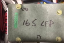
I have been part of the ebike community for over five years. I built two 16s4p battery packs using K-2 26650 energy cells (3.2v 3.2ah). The pack that’s causing today's problem was originally installed in the triangle of my back-up commuter ebike. The back-up ebike was in storage for approximately three months.

I need the great minds of this forum to assist me with the diagnosis and repair of a battery pack that I cannot charge using the BMS yellow wire (charger negative) and the pack red (positive). The BMS was purchased from Cell_man (Em3EV) over three years ago, along with a 48v 5ah charger.


I also use a Mastech 60v 20ah CC/CV power supply to charge the three ebikes in my stable. I cannot charge the battery through the BMS using the 48v charger or CC/CV. When I connect the charger, it immediately displays the green light. Same results when I attempt to charge the pack using the Mastech CC/CV through the BMS: there’s no current draw. The pack voltage does not increase using either charging source.

The identical 16s4p pack charges to 58.4 before the BMS shuts down the charger, or the Mastech power supply terminates the current. The cells of this pack were in service for months without a BMS as two 25.6v packs that I balanced every third charge cycle using an Imax8.

After purchasing the BMS from Cell_man, I chose not to remove the balancing wires from either of the two 25.6v packs before connecting them in series. This has allowed me to check the status of each cell with a Cellog8 without removing the all the duct tape.

My initial thought was a defective cell. I even purchase four replacement cells from Battery-Space in Richmond, however after checking each using the Cellog8 and my DMM, here are the cell voltages for the total pack, after a discharge of each 8s block using my Imax8:

1. 3.323
2. 3.331
3. 3.229
4. 3.329
5. 3.327
6. 3.329
7. 3.344
8. 3.339
9. 3.324
10. 3.327
11. 3.330
12. 3.340
13. 3.342
14. 3.336
15. 3.347
16. 3.339

When bypass the BMS, and charge the pack through the balance wires, the result is a healthy 58v, but without the BMS, a few of the cells were over 3.8v (3.65v is safe) until the bleed down using the Imax 8.

Shorts? Well, the negative (yellow) charging wire of the BMS continues to provide the SOC for the DMM and Cycle Analyst. Is it time to remove the duct tape from the pack and inspect the BMS? Thanks
 
yes. take the BMS out and i think this one has the big metal heat shield on top which is hard to remove but you may be able to isolate the mosfet legs to test it.

post up pictures.
 
Okay Dnum, about to unwrap this mummy after donning the requisite ppe! Will post pictures soon. Thanks
 
Okay, the pictures are helpful for identifying the BMS.

Em3EV 16s BMS Top.jpg


You're right about the existence of a metal cover, but anything other than a "nose test" is beyond my pay grade. No burnt areas or damaged wires were evident where it attaches to the pack. Still looks new and still has that new car smell. Should I remove the BMS from the pack and take it apart? Thanks
 

Attachments

  • Em3EV 16s BMS Label.jpg
    Em3EV 16s BMS Label.jpg
    34.1 KB · Views: 3,794
use an exacto knife,utility knife, razor blade, pocket knife, sewing pin, sharp pick, all of the above, and cut the glue on the nuts holding the paper down. you want the screw inside the nut to turn and use a small phillips screwdriver on the other side where the screw goes into the plate. big one will just strip it and you have to get the glue off the threads first with the razor.

if not then you will have to cut around the nuts on the right and peel the paper off the bottom of the pcb. on the right side only, where the mosfets are, first anyway. but getting the heat sink off may be difficult if the screw head gets stripped out.

you wanna test it while connected to the pack too so don't remove it from the battery. yet.
 
Hi Dnum,
I was able to remove the screws with a small Phillips screwdriver bit without stripping. No problem with the yellowish loctite substance around the nuts on the papered side of the BMS. I think choosing the right size screwdriver bit is the key.

Heat Shield Metal Cover Removal.jpg View attachment 1
 
in the lower left of the mosfets there are two labeled QC1 and QC2. those are the charging mosfets, all the others are for the output.

the legs of the mosfet are gate, drain, source from left to right. measure the voltage between the source leg and the gate on the charging mosfet and the output mosfet, both of them are all tied together in parallel so just one of the group is enuff.

use the 20V DC scale. no need to have it on the charger to do this, just measure the gate voltage. black probe on the source leg, red on the gate leg. or in the solder at the base of the leg.

if you woulda had problems getting the heat sink/shield off then we could have measured by probing from the other side. this is better. i noticed there is no thermal breaker either, which usually is part of this design but they are now using the digital controllers for running the BMS now too. this thing should work.

but measure the gate voltages, so we can tell if it is actually working and something else is broken.
 
The mosfet values are:
QC1= 0v
QC2= 0v
QC3 et al= -14.55
Is the negative voltage for the output mosfets normal? Thanks
 
you measured backwards i expect.

this confirms that the charging mosfet is turned off. so one of the cells is provoking the controller IC to turn off the charging mosfet because it sees HVC on one of the cells.

measure all of the cell voltages on the BMS where the sense wire is plugged in to see if you can find one cell that is at 3.60V or higher. or see if there is one that is much higher in voltage than the others.

your BMS may be keeping the charging mosfet turned off until the high cell is dropped in voltage so we need to know what the voltages of the cell is now. if we can find the high one and drain it down below 3.6V and cause the charging mosfet to turn on then we will know what has happened.
 
Is your question already answered from my previous post:

My initial thought was a defective cell. I even purchase four replacement cells from Battery-Space in Richmond, however after checking each using the Cellog8 and my DMM, here are the cell voltages for the total pack, after a discharge of each 8s block using my Imax8:

1. 3.323
2. 3.331
3. 3.229
4. 3.329
5. 3.327
6. 3.329
7. 3.344
8. 3.339
9. 3.324
10. 3.327
11. 3.330
12. 3.340
13. 3.342
14. 3.336
15. 3.347
16. 3.339

When bypass the BMS, and charge the pack through the balance wires, the result is a healthy 58v, but without the BMS, a few of the cells were over 3.8v (3.65v is safe) until the bleed down using the Imax 8.
 
I attempted to charge through the BMS after the discharge down to around ~3.33, but no change. The current values are:
1. 3.328
2. 3.334
3. 3.339
4. 3.333
5. 3.331
6. 3.329
7. 3.341
8. 3.326
9. 3.324
10. 3.321
11. 3.339
12. 3.339
13. 3.218
14. 3.451
15. 3.346
16. 3.338
 
the gate shoulda turned back on. there is some sorta common signal line from all 3 of those controller ICs for the gate that runs over to the right of the last IC and under that glob on the right side there is a transistor that has pulled the gate driver down. the gate drive is that top trace running across under the mosfets from right to left.

you can see it has two single spots of goop on top of it.

it would be interesting to scratch through the shellac on top of that trace and see if there is a voltage there on that trace but i expect it to be the same.

next you can try putting the charger on the pack and charging and see if the gate source voltage is pulled up from 0V when the charger is present. the charger negative is the source voltage so measure between the C- spot and the gate of QC1.

kinda grasping at straws. maybe one of the inputs of cell voltage to those controller ICs is considered high because of a bad contact in the sense wire plug but if you measured the cell voltages on the BMS where the pins are soldered down then they are all too low to provoke an HVC shut down.
 
Okay. Please let me know if trace I scratched is the correct one, and where I need to place my DMM probes for the testing you just recommended.


The BMS charging mosfets were just checked pursuant to your previous post and the QC1 & QC2 voltages are still at 0v. No voltage was detected when I placed the DMM positive probe on the gate of QC1 and the DMM negative probe on the charging post (yellow bms wire).

Troubleshooting idea: Are there any circumstances, other than a weak or overcharged cell, that will create such a condition? Can you replicate this problem? For example, if you wanted to prevent charging through the BMS how would you "turn off" the QC1 & QC2 voltage in a healthy and well-balanced battery pack, without starting a fire :D Okay to add in the fact that this is a battery that has been sitting fully charged for a couple of months.
 
yep, i think that is the gate drive trace. under either of those small black spots there may be another connection or transistors that can sink the gate drive if they detect over temp conditions but i see no thermocouple or other temp inputs.

i was hoping that by attaching the charger maybe it would pull the source down and the gate would then be turned on.

the only other desperate thing i would try is shorting the source and drain legs of the charging mosfet.

plug in your charger and it will show green led. not charging.

now use a wire or screwdriver and short the source leg on the right to the drain leg in the middle, nothing fancy, just bypassing the mosfet by going directly from source to drain even though the mosfet is still turned off.

see if it starts charging when you short the legs.
 
Test 1: After connecting the pack to the cc/cv power supply, I momentarily shorted the source and gate legs of the charging mosfet (QC1).

Result: The charging mosfet voltage did not change from 0v, nor was there a current draw displayed on the cc/cv power supply to indicate charging.

Test 2: I attempted to charge the battery pack using the 58.4v smart charger. I wanted to see if the smart charger's charging status led would change from green to red.

Results: Unfortunately, the customary change of the charge status led from green to red (charging) did not happen, despite the fact that my Cellog8 readings indicated SOCs of approximately 3.33v for the majority of the cells in this 16s battery pack. No cell was found to be out of range (under 2.5v or over 3.65v) and the voltages were not increasing from 3.3v with the pack still connected to the smart charger.

Test 3: I shorted the charging mosfet (QC1) while the pack was still connected to the smart charger.
Result: The smart charger turned on (fan noise, red leds, etc). But when I stopped shorting the source and gate legs of the charging mosfet (QC1) the smart charger's fan stopped and the status led returned to green.

What's next? Thanks
 
Considering the positive results when I shorted the charging mosfets, do I need to rig a switch to turn on the charging mosfets, while monitoring a Cellog (or set alarms) to prevent over-discharging the individual cells. Will this be the new normal for this pack, Dnum?

Shorting FETs Charge Method.jpg
 
not sure why you decided to short the gate to the source. your picture shows a screwdriver shorting the drain to the gate leg.

i explained in the early post, the legs of the mosfet when looked at face on, are gate, drain, source.

if you short the gate to the source it will turn off the mosfet. i asked you to see if the charger would turn on when you shorted the drain to the source.

now i am not sure what your measurements were of before.
 
Sorry about that. Last night I fully charged each cell to 3.6v. This morning I reconnected the charger and rechecked the voltages of the BMS mosfets:

1. QC1 (gate leg-source legs) = 0v
2. Output mosfet (gate leg-source legs) = 0.2v
3. Shorting the QC1 (drain-source legs) did cause the charger to turn on momentarily.
 
Paul of EM3ev offered the following in response to my 5/29/2015 email regarding the problem. I just read the response today. This battery pack is over two years old and is no longer a split pack. When it was a split pack, I used a K2 Energy K2B24V10EB 24v LifePo4 Battery BMS for charge and balancing, but that all ended when the 16s bms was from Em3ev was installed in January 2013:

"Hi John, Try charging the battery through the discharge leads. If it charges through the discharge leads but not through the charge leads, that indicates some sort of issue with the BMS or the signals being received by the BMS. If the cells are within spec, that suggests the BMS is at fault.

If the link between 2 series packs is disconnected whilst discharging, that can damage the BMS, destroying the cell sensing circuits on some of the channels. That may possibly be what happened and that is why we do not like to build split packs which use a single BMS. Thanks Paul"

When I tried to charge the pack through the discharge leads, using the blue BMS wire for the negative connection to charger instead of the yellow wire, the charger turned on (green to red led, fan noise).

I included in my reply to Paul's 5/29/2015 email: "Please review my recent post Need Help Diagnosing and Repairing a BMS, and respond with any additional advice. That way we will avoid stepping on each other’s toes and may better assists newbies with similar problems."

Thanks again
 
ok, if the charger turned on then that means the connections from C- to the battery is intact.

the output mosfets should still be turned on also. you had measured 14.5V before which is about right for 4S supplying the circuit current.

the charger should remain on if the S/D legs are shorted on the charging mosfet, since the output mosfets are the route that the charging current uses to reach the battery.

the source leg of the output mosfet is connected to the B- terminal through the current sense shunt resistor. i think it is a big surface mount resistor on the right side next to the black wire going to B-. that surface mount resistor could be cracked and any current through it would have a voltage spike which could cause the output mosfets to be turned off for overcurrent detection.

but there has to be a reason behind the shutdown of the charging mosfet. that is usually because of the high voltage on one cell.

ok, just read your post from paul, but is this a split pack now? do you have a connector between one pack and the other or is it a solid wire connection soldered between the B- of the top pack and the B+ of the lower pack?

we need to verify that the output mosfets are turned back on. it is always the source to gate voltage, left leg to right leg that turns on the mosfet. see if that voltage comes back when you remove the charger and if it turns off when you add the charger.

i would go back and measure each of the 16 cell voltages right on the BMS pcb at the base of the plug. see if there is an anomaly. there could be a bad connection when the plug is twisted or bad solder joint of the pins to the pcb. it could be a bad solder joint on the current sense shunt too but not as likely since they are pretty strong imo.
 
Full pack.jpg

According to my knowledge it is not a split pack. I have been charging and discharging the same battery pack through the same 16s BMS for over two years after joining the two 26.4v packs with nickel strips and copper solder braid.

Is this where I need to check the cell voltages:

pcb sense wires.jpg

Due to the spacing between wire terminals, my DMM probes appear to be too big to safely measure the cell voltages on the board. However, I think it's a necessary step because previous readings are all taken from the sense wires I used when this was a split pack. As stated in an earlier post, I elected not to remove them when the two 26.4v were permanently connected in series. The voltages I measure for each cell through the old pair of split pack sense wires (8s each) may not be the same as what the BMS detects through its sense wires for a 16s pack if the connections are faulty.

Sounds like I may have to unwrap gorilla tape from this "entire mummy" of a battery pack, Ugh!
 
no, do not measure anywhere but right on the pcb. turn it over and measure where the solder bump is at the base of the pins.

he is correct though in observing that open circuit between packs in series will destroy the BMS on the channel at the top of the lower pack.
 
I cannot access the pins due to the hard black stuff. Apparently, this pcb was manufactured to protect me from my own ignorance.

reverse pcb.jpg
 
I used a couple of safety pins to take measurements of the cell voltages as seen by the BMS.


The results are as follows:
1. 3.5
2. 3.6
3. 3.5
4. 3.5
5. 3.5
6. 3.4
7. 3.5
8. 0.3-1.3 (bouncing)
9. 3.4
10. 3.4
11. 3.5
12. 3.4
13. 3.5
14. 3.5
15. 3.5
16. 3.6

Do I need to unwrap the duct tape and recheck the sense wire for cell #8 (right at the point the packs were joined back in 2013)?
 
Dnum, I believe the problem is solved, but I need your confirmation. I found a detached sense wire between cells #8 and #9.


Detached sense wire.jpg

After reattaching the sense wire, the QC1 charging mosfet (gate-souce) voltage was measured at 0.1v. Next, I placing a dummy load on the battery pack, using a 250 watt heat lamp bulb for approximately 5 minutes.

When I removed the dummy load and reconnected the charging leads to smart charger it began to immediately charge the pack, but it stopped charging after only a few minutes. According to my watt meter, approximately 56 mah was returned to the battery. Do I need to apply a more rigorous test to determine if the problem is solved? I just hope that the disconnected sense wire did not result in permanently damaged to the BMS, as Paul was suggesting. This pack is over two years old, but the cycles are less than 100, since becoming a complete 16s battery pack.

UPDATE-I used the dummy load to bring the pack voltage down to around 53v, but the charging mosfet voltage did not change from 0v. The output mosfet voltage was 2v. After a few minutes the charging mosfet voltage returned to 0.1v and the output mosfets increased to approximately 15v. However, when I connected the smart charger, it would not charge continuously despite the lower pack voltage. I rechecked the cell voltages using the pcb and the cells were all within range (3.3v-3.5v). Thanks
 
Back
Top