My first post here on Endless Sphere, and it's a cry for help!
I've got a common port Daly R16J 14s BMS hooked up to a fresh battery build, and am not confident enough to plug it into my bike yet... I've been in touch with Daly but it's been slow back and forth and I don't think they are fully understanding me, so here's some background with the issue:
Daly R16J-GF12 14s 60A/30A smart BMS, BT Dongle (with power button that... doesn't function), USB-Monitor cable (3-pin connector labeled on BMS 'Monitor') - the Sinowealth tool works with this BMS but the PCMaster tool can only read params (some erroneously) and not write them at all, or calibrate - the PCMaster tool can only even communicate with the BMS when using the USB-UART cable which I had to order and wait for, and then it plugs into the BT dongle's port so I cannot view changes in the app made from the PC tool like I am able to do so with Sinowealth
14s4p 52V pack, 18Ah, 54A max CDR (controller set for a lower max current), cells charged up to ~4.05V balanced within 5mV of eachother, my connections are 5mil copper sheet + 0.1mm nickel tabs, 10AWG wire all around, XT90S connector on the battery pack.
The BMS gives relatively accurate current reading within 50mA when dicharging using a DC electronic load set to CC 2.6A
When I hook up my bench supply set to 58.8V and 2A to charge the pack (will probably charge at 4A but this is just testing values to verify things are working) it completely disregards the constant current limit of 2A and only tops out around 17.7xxV, bouncing around there but showing ~4.435A. The BMS never shows charge status or current, and the cell voltage on the pack looks like it slowly drops, but when unplugging rises back up again. Almost like it does when discharging with the DC load but not as dramatic.
Both my DC load & bench supply are good, work with other devices and I used the bench supply to balance the cell groups in the pack with the CC/CV working perfectly as expected. My DC load reads the correct voltage at the connector as does my DMM.
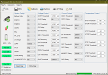
The only guides and documentation I could find regarding Sinowealth software doesn't touch on the IC types that feature params in the AFEReg tab as shown below. There is also a machine-translated Chinese-language version of the tab that gives a little more descriptive names than the English abbreviations for the parameters. I can't see any of these numbers corresponding with 14s to hit 17.7V and there's nothing in there that would suggest the BMS is being told to prevent charging, correct? Sorry for funky font, typed out version of machine translation follows the image
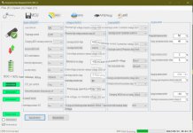
ENPCH - Precharge Control
ENMOS - Charging MOS Recovery Control
OCPM - Overcurrent MOS Control
BAL - MCU Control Balance
PF_CTO - Abnormal High Voltage Disconnection
LVcharge - Low Voltage Charging
LDRT - Load Release Delay
CTLC - CTL Pin Control
OCRA - Overcurrent Protection Timing Recovery
LockLoading - Load Lock (???)
UV MOSFET CTL - Undervoltage Shutdown Charge
Some things to note: BMS came with CADC Gain set to 370 & CADC Offset at 0. Sometimes when I calibrate 0 current it sets the Offset to 6, sometimes it sets it to 7. I have read from several sources the CADC Gain should be negative or it will read charge/discharge current inversely, but setting that value to -370 shows no discharge or charge current at all, and does not change any of the previously described situations when discharging (correct on DC load) or charging (unexpected values on bench supply)
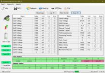
Info tab: (screen shot taken before charging up cell groups) - note the CHG_FET & DSG_FET being red or '0' value means they are functioning and not tripped. When discharging the DSGING field turns red or '0' to denote discharging status. CHGNG never turns red/0 when trying to charge via bench supply.
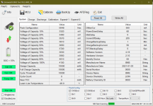
System tab - note the 'Identify Device' field has no entry (IC Name would go here), other screens I've seen show Manufacturer Name as 'Daly' and the 'Battery Chemistry ID' field a different value than 0000 for LION 'Device Chemistry' field
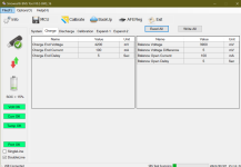
Charge tab - 'Charge End Current' is now set to 200mA and delay 60s as stated as one of the charge methods in my cells' datasheet and multiplied by 4 for the 4p pack. From what I have read 'Balance Open Current' is the minimum current required on the BMS to balance the cells. Some have had success getting it to balance the cells even when resting by setting this to 0mA but I don't bother - just as long as it's below my minimum charge current.
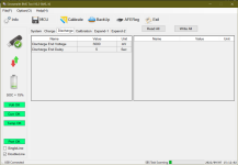
Discarge tab - I am using an Archon X1 with a Bafang Ultra M620, from what I can gather the LVC for a 52V config for this controller is 41.3V or 2.95V. With a 3000mV discharge voltage end and 5S delay I would expect the pack to read 3000mV holding for 5s would tell the BMS it's at 0% SoC - idea being never to even hit the LVP on either BMS or controller. I don't want to trigger any weird conditions that require a weird reset procedure I can't do while out on a ride, without a computer handy.
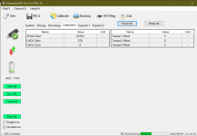
MCU Calibration tab - this 'VPack Gain' gives accurate voltage readings as my DC load within 40mV or so. My DMM only goes does 3 digits but shows the same, rounding accounted for. 370 'CADC Gain' is what it shipped with and 6 'CADC Offset' is what it spit out that time when calibrating 'Zero Current' in the Calibrate tab. Whenever I am trying to calibrate 'Work Current' I am not seeing any change in value for the 'CADC Gain' value, I am using a negative value in the Calibrate field and it shows successful - a positive while discharging fails.
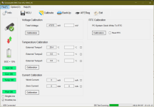
Calibrate tab
I've got a JBD on the way but seems I cannot have the BT & USB hooked up to that at the same time, and it doesn't appear to have a power switch on the BT dongle or a connector for the power switch at all. I printed my pack parts so the BT dongle/switch would hang outside of the sealed pack next to the power connector, but if the power button doesn't function or there is none I'd like to swap the USB plug to be accessible & installed and seal up the BT dongle under heat shrink. Not sure I pulling the BT dongle off the plug will put the Daly to sleep, but the damn thing never goes to sleep and it powers on and is detectable as soon as the balance harness is plugged in. Hoping the JBD is cleaner and easier to use but I bought 5 of these directly from Daly for a 'good price' per unit, and would really like to not be stuck with 5 paperweights if I can help it. I really do like how hefty and sealed up the Daly is, wire placement also seems a little more convenient and the form factor easily works for my builds. Is my damn bench supply simply not starting with a high enough voltage and fighting with the BMS? I have a 2A 'dumb' charger for a UPP I could hook up to the battery but am wary of what may happen since I can't really see any info from that charger. I only bought the $300 DC load to see if it was a calibration issue with these BMS's but this is not the case (maybe?) so I'm already pretty unhappy with my Daly experience thus far, don't really want to have to try my luck with a MeanWell LED driver and Wattmeter as this is starting to become a ridiculous amount of money to 'save' on building my own packs vs buying custom.
I just wanna ride!
Any help is greatly appreciated
I've got a common port Daly R16J 14s BMS hooked up to a fresh battery build, and am not confident enough to plug it into my bike yet... I've been in touch with Daly but it's been slow back and forth and I don't think they are fully understanding me, so here's some background with the issue:
Daly R16J-GF12 14s 60A/30A smart BMS, BT Dongle (with power button that... doesn't function), USB-Monitor cable (3-pin connector labeled on BMS 'Monitor') - the Sinowealth tool works with this BMS but the PCMaster tool can only read params (some erroneously) and not write them at all, or calibrate - the PCMaster tool can only even communicate with the BMS when using the USB-UART cable which I had to order and wait for, and then it plugs into the BT dongle's port so I cannot view changes in the app made from the PC tool like I am able to do so with Sinowealth
14s4p 52V pack, 18Ah, 54A max CDR (controller set for a lower max current), cells charged up to ~4.05V balanced within 5mV of eachother, my connections are 5mil copper sheet + 0.1mm nickel tabs, 10AWG wire all around, XT90S connector on the battery pack.
The BMS gives relatively accurate current reading within 50mA when dicharging using a DC electronic load set to CC 2.6A
When I hook up my bench supply set to 58.8V and 2A to charge the pack (will probably charge at 4A but this is just testing values to verify things are working) it completely disregards the constant current limit of 2A and only tops out around 17.7xxV, bouncing around there but showing ~4.435A. The BMS never shows charge status or current, and the cell voltage on the pack looks like it slowly drops, but when unplugging rises back up again. Almost like it does when discharging with the DC load but not as dramatic.
Both my DC load & bench supply are good, work with other devices and I used the bench supply to balance the cell groups in the pack with the CC/CV working perfectly as expected. My DC load reads the correct voltage at the connector as does my DMM.
The only guides and documentation I could find regarding Sinowealth software doesn't touch on the IC types that feature params in the AFEReg tab as shown below. There is also a machine-translated Chinese-language version of the tab that gives a little more descriptive names than the English abbreviations for the parameters. I can't see any of these numbers corresponding with 14s to hit 17.7V and there's nothing in there that would suggest the BMS is being told to prevent charging, correct? Sorry for funky font, typed out version of machine translation follows the image


ENPCH - Precharge Control
ENMOS - Charging MOS Recovery Control
OCPM - Overcurrent MOS Control
BAL - MCU Control Balance
PF_CTO - Abnormal High Voltage Disconnection
LVcharge - Low Voltage Charging
LDRT - Load Release Delay
CTLC - CTL Pin Control
OCRA - Overcurrent Protection Timing Recovery
LockLoading - Load Lock (???)
UV MOSFET CTL - Undervoltage Shutdown Charge
Some things to note: BMS came with CADC Gain set to 370 & CADC Offset at 0. Sometimes when I calibrate 0 current it sets the Offset to 6, sometimes it sets it to 7. I have read from several sources the CADC Gain should be negative or it will read charge/discharge current inversely, but setting that value to -370 shows no discharge or charge current at all, and does not change any of the previously described situations when discharging (correct on DC load) or charging (unexpected values on bench supply)
Info tab: (screen shot taken before charging up cell groups) - note the CHG_FET & DSG_FET being red or '0' value means they are functioning and not tripped. When discharging the DSGING field turns red or '0' to denote discharging status. CHGNG never turns red/0 when trying to charge via bench supply.

System tab - note the 'Identify Device' field has no entry (IC Name would go here), other screens I've seen show Manufacturer Name as 'Daly' and the 'Battery Chemistry ID' field a different value than 0000 for LION 'Device Chemistry' field

Charge tab - 'Charge End Current' is now set to 200mA and delay 60s as stated as one of the charge methods in my cells' datasheet and multiplied by 4 for the 4p pack. From what I have read 'Balance Open Current' is the minimum current required on the BMS to balance the cells. Some have had success getting it to balance the cells even when resting by setting this to 0mA but I don't bother - just as long as it's below my minimum charge current.

Discarge tab - I am using an Archon X1 with a Bafang Ultra M620, from what I can gather the LVC for a 52V config for this controller is 41.3V or 2.95V. With a 3000mV discharge voltage end and 5S delay I would expect the pack to read 3000mV holding for 5s would tell the BMS it's at 0% SoC - idea being never to even hit the LVP on either BMS or controller. I don't want to trigger any weird conditions that require a weird reset procedure I can't do while out on a ride, without a computer handy.

MCU Calibration tab - this 'VPack Gain' gives accurate voltage readings as my DC load within 40mV or so. My DMM only goes does 3 digits but shows the same, rounding accounted for. 370 'CADC Gain' is what it shipped with and 6 'CADC Offset' is what it spit out that time when calibrating 'Zero Current' in the Calibrate tab. Whenever I am trying to calibrate 'Work Current' I am not seeing any change in value for the 'CADC Gain' value, I am using a negative value in the Calibrate field and it shows successful - a positive while discharging fails.

Calibrate tab

I've got a JBD on the way but seems I cannot have the BT & USB hooked up to that at the same time, and it doesn't appear to have a power switch on the BT dongle or a connector for the power switch at all. I printed my pack parts so the BT dongle/switch would hang outside of the sealed pack next to the power connector, but if the power button doesn't function or there is none I'd like to swap the USB plug to be accessible & installed and seal up the BT dongle under heat shrink. Not sure I pulling the BT dongle off the plug will put the Daly to sleep, but the damn thing never goes to sleep and it powers on and is detectable as soon as the balance harness is plugged in. Hoping the JBD is cleaner and easier to use but I bought 5 of these directly from Daly for a 'good price' per unit, and would really like to not be stuck with 5 paperweights if I can help it. I really do like how hefty and sealed up the Daly is, wire placement also seems a little more convenient and the form factor easily works for my builds. Is my damn bench supply simply not starting with a high enough voltage and fighting with the BMS? I have a 2A 'dumb' charger for a UPP I could hook up to the battery but am wary of what may happen since I can't really see any info from that charger. I only bought the $300 DC load to see if it was a calibration issue with these BMS's but this is not the case (maybe?) so I'm already pretty unhappy with my Daly experience thus far, don't really want to have to try my luck with a MeanWell LED driver and Wattmeter as this is starting to become a ridiculous amount of money to 'save' on building my own packs vs buying custom.
I just wanna ride!
Any help is greatly appreciated

