Need Help Diagnosing and Repairing a BMS

the charge will stop when one cell reaches the HVC. so you just have to watch the cell voltages while it is charging and find the one that goes to HVC first and drain charge off of it.

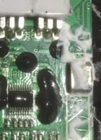
do no measure the voltages from the back side of the sense wire plug. measure the voltage at the base of the pins soldered into the pcb. stick the probe in the solder where the pin sticks out the back side. it is not hard to keep them separate. that is why they have a sharp point. so it will stick in the solder.
 
Okay. The duck tape has been cut away so I can access the individual cells. I used a small wood screw to short the charging mosfet (screw was placed between the source and drain legs) in order to charge the battery after the dummy load had run for approximately 1 hour. I decided to use the cc/cv power supply to limit the voltage to 58.4v. The pack charged to 57v before I removed the charging leads from the cc/cv power supply.

When I checked the cell voltages of each cell using DMM probes, 15 cell voltages were between 3.54v - 3.56. Cell #10 was out of range at 3.7v.

However when I measured cell voltages using the posts on the pcb, as you advised in your last reply, cells #7 and #8 bounced around between 0v - 1.2v. For those two cells, I could not never get a constant reading.

I used the Imax8 discharge function to drop cell #10 to around 3.5v, but the charging mosfet voltage remained at 0v. The output mosfet voltage climbed from 2.0v to 15v.

There's is no agreement between the SOC reported by the bms and my direct measurement of the cell voltages. The voltages taken using the pcb sense wire pins or solder pads, does not agree with the measurements derived from the individuals cell using the DMM, or the cell voltages taken off of a safety pin inserted in the back of the pcb sense wire terminals.
 
SOLVED! Thanks Dnum, I was getting a little frustrated, but your skill and focus helped motivated me to stay the course. A couple of the sense wires I reattached were most likely pulled away by the unwrapping of the gorilla tape. Reattaching those two wires provided only false hope.

THE SOLUTION: The problem persisted because the connection between a sense wire in the middle of the pack and the pcb was compromised by the hot glue used in building the pack, which you had concluded in your last post. After pulling the sense wire out of the glue and soldering it in the correct place, everything returned to normal. The following cell voltages were taken from the pcb terminals:

1. 3.5
2. 3.5
3. 3.5
4. 3.5
5. 3.5
6. 3.4
7. 3.5
8. 3.5
9. 3.6
10. 3.5
11. 3.5
12. 3.5
13. 3.5
14. 3.5
15. 3.5
16. 3.5

The QC1 voltage after the repair was 0.1v (not connected to charger) and the output mosfet voltage was 0.2. When I connected the battery pack to the smart charger, charging continued until the pack was fully charged. Thank you again. :D
 
that BMS is a nice unit and will balance your pack up to full charge. did you measure the output voltage of the charger?

57.6V is the balanced voltage since i am sure they use 3.60V/cell so your charger can be set to 58V and force them all to the same 3.60V level but you gotta leave it charging for awhile to do that since the balancing currents take time.

once it is fully balanced you could even do a discharge into a dummy load like a radiant heater through a wattmeter to measure the capacity and find the lowest capacity cell that hits the 2V LVC first.
 
In order to remove the heat shield from atop the BMS, I had to cut through a glob thick white putty. It covered what I believed to be the heat sink. Can I replace it with thermal paste or is it just thermal conductive silicon sealant with low adhesive properties?


Attachments

  • 16S em3ev bms heat sink.jpg
    16S em3ev bms heat sink.jpg
    44.8 KB · Views: 1,114
it will be ok to just screw it back on. i doubt if the heat sink makes any difference. but make sure the paper cover goes onto the backside since those traces can short to the battery.

that small square thingy under the white goop is the current sensing shunt resistor. it gets hot a little bit just like the ones inside the wattmeters.
 
Thanks again Dnum. I always learn more from problem solving than simple reading the forums. I plan to parallel this pack with an identical one that is already installed in the triangle pack of my commuter bike. Heavy bike with 25 ah of lifePo4 26650 batteries.

This long rectangular pack, just repaired with Dnum's assistance, will be placed on the top tube of the commuter. Unfortunately, I may need to dispense with my Cane Creek suspension seat apparatus in order to lower my seat. I don't like the idea of straddling 16s of lithium batteries at every stop.

The next build was delayed until the BMS/battery problem was resolved. It includes a 18 fet controller I received from Edward Lyen a couple weeks ago. Ed is suggesting a NCM battery from BatterySpace/AA Power in Richmond, Ca, but I haven't read any reviews of their NCM packs on this forum.

I recently had a very positive experience with Battery Space. I had anticipated the need to replace cells in the problem pack so I ordered four 26650 cells with tabs. The batteries arrived without the tabs. Battery Space immediately express shipped four 26650 cells with tabs and followed up with an email of apologizing for their mistake. BatterySpace also informed me that I can keep the cells shipped without the tabs.

The last time I paralleled two identical packs with separate bms, Terry of Hightekbikes (SF) advised me to use Shottky diodes. I found and ordered ten 100v 30a schottky diodes from Digi-Key (V60100C).

View attachment 1

I used an old style push/pull headlight switch to separate the packs during charging.

headlight switch.jpg
 
do not use diodes if they are identical packs. do not put a switch between them. connect them in parallel at the P- spot on the BMS and B+.

you only use diodes if you have two different types of batteries such as combining SLA and lifepo4 in parallel or lipo and lifepo4 in parallel but in the case of paralleling the lipo and lifepo4 you would only do that to prevent one battery from overcharging the other when charging, otherwise they can be in parallel without diodes since they have equivalent characteristics.

the diodes stuff is totally made up by people who do not think about what the batteries are doing. mainly because they don't know better and have just read it somewhere because this misinformation is promulgated here on the sphere.
 
I can recall a raging debate in this forum a couple of years ago over using diodes when paralleling packs with the same chemistry.

I am not completely sure about this, but there were pdf instructions from Ping passed around that included the uses of diodes. Still, not every agreed with the diode thing, especially for close to identical packs. Both of my packs are 51.2 v 12.8 ah and same chemistry. I think I'll follow your advice this time.

Now, how does one parallel using the two pcbs, and how does it effect charging the two packs?. Please refer me to the relevant forum, if deemed appropriate. Thanks Dnum
 
if you charge both batteries which are in parallel then if the MS has a separate charging lead, C- as your battery does, then the two BMS must be disconnected from each other at the P- spot where the drains of the BMS output mosfets are connected in parallel.

this means that while charging, and only while charging with the same charger to both batteries, you have to disconnect one or the other battery pack from the other at P-. you can do this by just unplugging one battery from the harness that connects both to the controller at P-.

i use diodes on my battery because i have a 72V 100Ah SLA pack in parallel with the two lithium packs i use. i put ten 10A 45V axial diodes together in parallel to make one 100A didoe which is able to dissapate all of the heat created in the diodes by the current passing through them.
 

Attachments

  • DSC01808.JPG
    DSC01808.JPG
    30.7 KB · Views: 1,109
Thanks for sharing how you employ diodes with your build. Your axial diodes appear to be a more durable form factor the T0220 I used (legs break easily). Do you keep the axial diodes exposed to a flow of air to aid in heat dissipation?

PLEASE CONFIRM: I need to place the switches on the negative discharge lead (P-) of each paralleled pack to allow charging with the same charger. However, if I used two power sources to simultaneously charge the two packs (cc/cv power supply & reg charger) is there a need to separate the packs at -P (neg discharge wire to controller)? Thanks
 
you have to separate the two BMS at the P- spot if there is a separate charging input called C-. if you charge through the P- lead on the BMS then the design is different and disconnecting is not essential but recommended.

the reason is that the charging current will not be turned off when one cell reaches HVC because the charging current can flow through the adjacent BMS if they are still connected through the drains on the output mosfets, which is the P- terminal.

i use the axial diodes because they can more easily dissipate the heat generated when the current flows through them. plus they are super cheap. these are just regular schottky diodes for solar panels i bot on ebay. i can find the seller if you decide you need some but if you do not have a lead acid pack in parallel then do not use them. diodes are a fire risk and eat up a lot of power.

i have asked li ping to remove his instructions but he makes good money selling the diodes so i doubt if he will.

i also use a similar 100A diode array on the drains of the lifepo4 BMS that connects to my lipo pack so that when i am charging it is not possible for the lifepo4 pack to accidentally overcharge my lipo pack when the lipo pack has reached HVC and shuts off.

that is a little more complicated for most to understand so unless you build a 24S lifepo4 pack and put it in parallel with a 21S lipo pack it would not be of any value to you for me to try to explain it. but for discharge i have a 100A anderson connector i connect to bypass the diodes. this allows the batteries to operate as one in parallel without losing power through the diodes on the base of the lifepo4 pack.
 
Back
Top