Need help with a 24V to 48V boost converter.

TylerDurden

100 GW
Joined
Jan 4, 2007
Messages
7,176
Location
Wear the fox hat.
Hi folks,

As you may know, I'm messing around with the 24v drill-packs.

To make the process complete, I need help on making a step-up converter to get more kick from the packs, so I can run a 36V motor at 48V. I can parallel a number of 24V packs to get plenty of current.

I'd like help with the circuit design. I can solder and fabricate fairly well and I can read a schematic decently.

I've looked at a few circuits, but most I have found are for low power applications. Ebikes are a bit bigger, powerwise.

The closest thing I've found so far is a design for a fuel-cell converter with 24V battery backup that delivers 48V to an inverter. Perhaps with some help I can isolate the boost converter portion of the circuit.

The attached file is the fuel-cell design research paper. Some of the pix are fuzzy, but some of the components are discernable.

Any help or links are greatly appreciated.

:D
 
As you may know, I'm messing around with the 24v drill-packs.

That's how it starts... :)

Are you thinking the BMS will be a problem if running the packs in series? You know you'll lose a lot of efficiency with a DC-DC converter.

Here's a 24-->48v converter, but only rated for 1.5 amps continuous:
http://www.powerstream.com/dc12-48.htm

Could put 20 in parallel, right?
:D
 
Hi Tyler, are you not wanting to go with a 2s2p configuration because you're worried the BMS might blow?

If you can't bypass the BMS on the output like people have done for the DeWalt packs, maybe it would be easier to just return them to Home Depot and get the Milwaukees instead.
 
Yeah,

The FETs are only rated for 40V.

I can open the packs and hack around the BMS, but the elegant solution is a step-up converter. If we get that figured out, anybody might be able to use any kind of drill-packs for as much power as needed.

Let's say the converter even has adjustable outputV... I might have (hypothetically) sixteen 24V 3 Ah packs, that could be simply 24Ah @48V or 12Ah @96V (less the conversion losses).

I know the tradeoff is a sacrifice of efficiency, but that is easily resolved by just adding another pack or two. Consider this scenario: if I just need to buzz a couple of miles to pick up a veggie-pizza, I throw a couple of packs on the bike and go... But if I need to go across town and back, plus stop by the post office; I throw eight or ten packs into the pot.

I can probably use a solar charge controller for a 48V system, but it would be much cooler to build something.
100_c40.jpg
http://www.xantrex.com/web/id/72/p/1/pt/25/product.asp

http://store.altenergystore.com/DC-...ers-Eq-2448-30A-2448-UpDown-Converters/p1295/

:arrow: Plus, if different voltage inputs could be integrated into a current-based throttle/controller, then we really got something.
 
So what is the practical maximum efficiency of a high power DC-DC converter? For lower speeds, would it offset the PWM losses of short duty cycles?
 
Lowell said:
So what is the practical maximum efficiency of a high power DC-DC converter? For lower speeds, would it offset the PWM losses of short duty cycles?

I think something like 85%...(?)


:?
 
Connecting packs in series won't do much for BMS as you already have a number of cells in series to start with. Go for 2s2p to get the volts.
 
until u get it,
use up 1 sla in series.
how bad r they?
 
Matt: Dang skippy!! The SLAs are fine... I just hate em. But I like em better now as boost-packs. :D

Maxwell, I'm not sure I understood. The FETs in the BMS are rated Vdss 40V, so two packs in series without bypassing the BMS could result in damage if a FET opens?

I want to keep the packs stock, to use the stock chargers and enjoy the lifetime service on the packs... I'm spending more upfront so I don't have to spend any more later (I hope).

8)
 
Hi Matt, if the FETs can only handle 40v, if he puts 1 SLA in series, he is still looking at the same problem as connecting his packs 2s2p... The FETs will blow just the same.
 
Lowell said:
If the packs have a lifetime warranty, it doesn't really matter if the FETs blow up does it? :D

Well, the idea is to go places and do things with clean power... I'll leave the pyrotechnics to Fechter. :lol:

If I can run my bike and my power tools with the same packs, why not more? (Look at KnightMB... he even runs his weedwhacker and mower with batteries.)

480 watts for 1 hr will charge 4 packs. $700 in solar panels will supply enough power to run the chargers each day. If I want to use more packs, I just get some more panels. ($200/45w @12Vnom.)

:D
 
jondoh said:
Hi Matt, if the FETs can only handle 40v, if he puts 1 SLA in series, he is still looking at the same problem as connecting his packs 2s2p... The FETs will blow just the same.
Hmmm...I am thinking "no they won't".

Think:

The packs' FETs won't see but their own pack's voltage

yes? no?

yes
 
The Fechtmaster hinted that IF a FET opened things could get interesting. Then a pack could see total voltage. I presume this could apply to any power tool packs used in series. To start on the safe side, I'd not want to exceed the rating of the FETs.

But adding one 12V SLA in series to the 24V parallel packs should only be 36V, so that might be ok (as long as I dont go WOT like Reid, and smoke the 24V unite I'm currently using.

Here's a nice convertor:

60A, 48V

tristar-white-200.gif

http://www.morningstarcorp.com/products/TriStar/

:)
 
That looks like a solar charge controller. I don't think it will work like a dc-dc converter. A voltage boosting controller is possible, but it would be complicated and have lots of efficiency loss. Let me think about that one.

It would be easier to rewind the motor to half the turns.

It would be nice to know what conditions will cause the BMS FET to go open. Over current would be one, which could be avoided by having the right current limit, and maybe a fuse for backup.

Undervoltage might be another, also possible to avoid with the right controller low voltage cutout.

All charging conditions won't matter, since the packs would be on the stock charger at that point.

I think if you get the controller current limit and LVC set right, the BMS will never need to open the FET (and self-destruct).
 
Ja, it is a charge controller, but it also a load controller...

http://www.morningstarcorp.com/products/TriStar/info/TS_Manual.pdf

Operating Modes

There are three distinct and independent operating modes programmed into each TriStar. Only one mode of operation can be selected for an individual TriStar. If a system requires a charging controller and a load controller, two TriStars must be used.

Solar battery charging
The energy output of a solar array is used for recharging the system battery. The TriStar manages the charging process to be efficient and to maximize the life of the battery. Charging includes a bulk charging stage, PWM absorption, float and equalization.

Load control
When set for load control, the TriStar powers loads from the battery, and protects the battery from over-discharge with a current compensated LVD low voltage load disconnect).

Diversion charge control
In diversion mode, the TriStar will manage battery charging by diverting
energy from the battery to a dedicated diversion load. The energy source is typically wind or hydro.


[Regarding Load control]

This section describes the user selectable load control settings (5.1) and the low voltage load disconnect (LVD) warning indications (5.2). Load information and general cautions are provided in the remaining sections.

5.1 Load Control Settings
The primary purpose of a low voltage load disconnect function (LVD) is to protect the system battery from deep discharges that could damage the battery. In the Load Control mode, the TriStar provides for seven standard LVD settings that are selected by the DIP switches. These are described in the table below. Custom LVD settings are possible using the PC software (see Section 7.0).

DIP 12V 24V 48V Battery 12V 24V 48V
Switch LVD LVD LVD SOC% LVDR LVDR LVDR
off-off-off 11.1 22.2 44.4 8 12.6 25.2 50.4
off-off-on 11.3 22.6 45.2 12 12.8 25.6 51.2
off-on-off 11.5 23.0 46.0 18 13.0 26.0 52.0
off-on-on 11.7 23.4 46.8 23 13.2 26.4 52.8
on-off-off 11.9 23.8 47.6 35 13.4 26.8 53.6
on-off-on 12.1 24.2 48.4 55 13.6 27.2 54.4
on-on-off 12.3 24.6 49.2 75 13.8 27.6 55.2
on-on-on Custom Custom Custom
Table 5.1

The table above describes the standard selectable LVD battery voltages for 12, 24 and 48 volt systems. The LVDR values are the load reconnect setpoints. The “Battery SOC %â€￾ provides a general battery state-of-charge figure for each LVD setting. The actual battery SOC can vary considerably depending on the battery condition, discharge rates, and other specifics of the system.

NOTE: The lowest LVD settings are intended for applications such as telecom that only disconnect the load as a last resort. These lower LVD settings will deeply discharge the battery and should not be used for systems that may go into LVD more than once a year. The LVD values in the table above are current compensated. Under load, the battery voltage will be reduced in proportion to the current draw by the load. A short-term large load could cause a premature LVD without the current compensation. The LVD values in the table above are adjusted lower per the following table:

TS-45 TS-60
12V –15 mV per amp –10 mV per amp
24V –30 mV per amp –20 mV per amp
48V –60 mV per amp –40 mV per amp

As an example, consider a 24V system using a TriStar-60 with a 30 amp load. The LVD will be reduced by 0.02V (per the table above) times 30 amps. This equals –0.6V. A DIP-switch selected LVD of 23.4V would be reduced to 22.8V in this example. Note that the LEDs are linked to the LVD setting, so the LEDs are also current compensated.

After an LVD, the load reconnect voltages are 0.25 volts per battery cell higher than the LVD (for example, in a 12V system the LVDR would be 1.5 volts above LVD). Battery voltages can rise quickly after an LVD, typically from 1.0 to 1.3 volts or more (12V system). The LVDR value must be high enough to avoid cycling in and out of LVD.

5.2
LVD Warning
When the battery is discharging and the green LED changes to the next state (G-Y LEDs on), there are four remaining transitions to LVD (refer to the LED indications in Section 3.3). Each of these LED displays will serve as a warning of an approaching LVD. The final warning is a blinking red LED state. The amount of time from the initial G-Y display until the load disconnect will depend on many factors. These include:
• The rate of discharge.
• The health of the battery
• The LVD setting
For a “typicalâ€￾ system with a healthy battery and an LVD setting of about 11.7 volts, there could be approximately 10 hours per LED transition. The LVD would occur about 40 hours from the first G-Y display (under constant load with no charging).

Another significant factor affecting the warning time is the LVD voltage setpoint. Lower LVD voltage settings may result in the battery discharging 70% or 80% of its capacity. In this case, the battery’s very low charge state will result in the voltage dropping much faster. At the lowest LVD settings, there could be as little as 2 or 3 hours of warning between LED transitions for a healthy battery.

The amount of time it takes to transition through the LEDs to LVD can vary greatly for different systems. It may be worthwhile to measure the time it takes for your system to transition from one LED state to the next. Do this under “typicalâ€￾ discharging loads. This will provide a good reference for how long it will take for your system to reach LVD. It can also provide a benchmark for judging the health of your battery over time.

5.3 Inductive Loads (Motors)
For dc motors and other inductive loads, it is strongly recommended to install a diode near the controller. Inductive loads can generate large voltage spikes that might damage the controller’s lightning protection devices. The diode should be installed near the controller, and in the orientation shown in the diagram on the next page:

The specifications for the diode follow:
• a power diode
• rated equal or greater than 80 volts
• rated equal or greater than 45 amps (TS-45) or 60 amps (TS-60)
For large inductive loads, a heat sink for the diode may be necessary.

5.4 General Load Control Notes
In addition to the inductive loads discussed above, there are a few other load issues that require attention:

5.4.1 Inverters
Inverters should never be connected to the TriStar.

5.4.2 Parallel TriStars
Two or more TriStars should never be put in parallel for a large load. The controllers cannot share the load.

5.4.3 Reverse Polarity
If the battery is correctly connected (LEDs are on), the load should be connected very carefully with regard to polarity (+ / –). If the polarity is reversed, the controller cannot detect this. There are no indications.
Loads without polarity will not be affected. Loads with polarity can be damaged. It is possible that the TriStar will go into short circuit protection before the load is damaged. If the LEDs indicate a “shortâ€￾, be certain to check for both shorts and reversed polarity connections. If the controller does not go into short circuit protection, the loads with polarity will be damaged.


8)
 
Cool beans...

Even a non-electronic putz like myself can appreciate the simplicity of the Linear document:

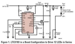
The LTC3783 has all of the functions that are normally required to run an LED string: an accurate current regulation error amplifier, a switch mode power supply (SMPS) controller with FET drivers, and two different ways to control the brightness of the LED string.

The current regulating error amplifier uses the voltage drop across a sense resistor in series with the LED string to precisely regulate the LED current. The SMPS control portion of the LTC3783 takes advantage of current mode operation to easily compensate the loop response of the many possible topologies such as boost, buck, buckboost, flyback and SEPIC. The integrated FET drivers allow fast switching of the power MOSFETs that are needed to efficiently convert input power to LED power without having to add external gate drive ICs.

Figure 1 shows a boost configuration using all off-the-shelf components. The input voltage, which ranges from 9V to 18V, is boosted to an LED string voltage of 30V to 54V. The LED string can consist of twelve, 700mA LEDs of any color in series for a total of up to 38W of LED power. At an input voltage of 18V and an LED string voltage of 54V, this circuit achieves an astounding power efficiency of over 95%! This high efficiency results in no greater than a 25°C temperature rise for any circuit component.


:?: Can the IC be used to control/deliver the kind of currents ebikes gobble up?
 

Attachments

  • LinerarIC1.jpg
    LinerarIC1.jpg
    30 KB · Views: 5,004
All the heavy current pieces seem to be external to the IC...so it would seem so.......still have to track down those bits though.......sure looks like it would beat my relays.. ....and their curve shows around 90% efficiency BM (before motor :lol: )
 
OK you will see the full pack voltage accross the FETs, however...

A) the packs will be getting flat, well one anyway, reducing the voltage seen.

B) All components are rated a bit under what they can really take.

C) It won't be ther for long.

D) If you are going along you can subtract the BEMF form the motor.

E) FETs usually fail short, you won't notice.

F) Put a volt meter accross each pack and do a human BMS as well, much cheaper than a coverter.

If you want a converter use the LTC3703, buck, boost and syncronous for up to 95% efficiency.
 
By using a FET gate driver, you can fan out the gate signal to a bunch of FETs and get as much current as you want. A brushed motor controller has most of the pieces you need, it would just need to be reconfigured.
You could take the gate output from the LTC3783 and feed it to the gate driver in a cheap scooter controller and have a nice high current switch.

The inductor is the tricky part. It needs to be really big to get big amps.
Ones I've seen are torroids with multiple parallel windings. The inductor has to take the full input current, so it will be a major source of loss if the resistance is too high.

There's a way to calculate the inductance needed for a given load and switching frequency, but I don't know exactly what it is.

The filter capacitors will need to take lots of ripple currrent, so they need to be beefy.

95% efficiency at 700ma is one thing, but trying to get 30 amps or more will likely be less efficient.
 
Ya, the inductor is the key...higher frequency will help...as long as the loss is less than my relay contact string, I think I'll be ahead of the game as this can give a true current control.....my preference would be power-out control and I think this would do it w/ an added PIC...but that's downstream at this point.......
 
Wow...that's right on target ! Limited in I, V, or both....just need an algorithm for max eff........

A bit pricey though......I was thinking the same thing could be made out of a 12V to 120VAC inverter (1 KW)
 
Back
Top