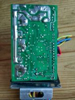
Need help with KU65 from bms ( different from others )

Decagrog

1 mW
Joined
Mar 9, 2016
Messages
10
Hi all,
I've finally received the KU65 controller for my project ( I'm building a kepler-like friction drive), so I planned to follow the avdweb blog modification http://www.avdweb.nl/solar-bike/electronics/ku63-motor-controller.html#h17-ku-63-modification-board but with my surprise my controller is quite different from the KU63 and the KU65 that other users of the forum have.

To keep short the schematic seems different and there's any label on the pcb ( just a http://www.szktdz.com ), the chip is also different, it's a cr8f6126t and I can't find any datasheet on the web :x so basically I'm in a dead spot!
Someone have already modified this controller and can give me some advice? Or it's better if I sell it and buy another KU65 hoping to get the most common version?

I attached a couple of pic
Thanks!
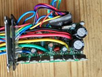
IMG_20160418_191457_HDR.jpg
IMG_20160418_191512_HDR.jpg
 
Little update:
I've made some other research also on other forums (es: pedelecsforum.de where Albert@avdweb is an active user) but didn't found any useful info, apart the fact that seem a new circuit revision for the KU65 controllers.

I need for sure to change the UVL since I would like to use 6S batteries and by default the controllers cut @27.7V, I suppose I can try to identify if there's a voltage divider circuit and try to change the resistors but without any datasheet this is as far as I can go...surely I'll not be able to made others usually mods.

Since those controllers are very cheap I can ditch the KU65 buy a S06S from bms (hoping that they didn't upgraded also this one) but I hate to way another month for the delivery :x ... any suggestion?
 
LewTwo said:
That does not look significantly different from the KU65 controler I received from BMS last week.

Hi, did you opened yours and made some modifications I mentioned above?
 
After a close look to the traces and components I've managed to spot the voltage limit circuit, it's basically the same on classic KU65/KU63 only just with a different R50 value.

I've attached a photo with the identified components and their underlying traces if could be useful to someone, but be sure to double check if your controller is the same

Y8B0pix.jpg


In my case the R50 value is 15K, UVLimit should be 27,7V (i suppose!) and I would like a new UVlimit of 17V , with the formula on avdweb the new value should be:

R50new = R50old * UVnew / UVold + R55 * (UVnew / UVold -1)
15000 * 17 / 27.7 + 1200 * (17/ 27.7 - 1) = 8741 = nearest good value 9.1K
 
Decagrog said:
LewTwo said:
That does not look significantly different from the KU65 controler I received from BMS last week.

Hi, did you opened yours and made some modifications I mentioned above?
I opened it when it failed to deliver 5 volts to the controller. Then I ordered a replacement. I will try to repair it when I have more time.
 
Decagrog said:
After a close look to the traces and components I've managed to spot the voltage limit circuit, it's basically the same on classic KU65/KU63 only just with a different R50 value.

In my case the R50 value is 15K, UVLimit should be 27,7V (i suppose!) and I would like a new UVlimit of 17V , with the formula on avdweb the new value should be:

R50new = R50old * UVnew / UVold + R55 * (UVnew / UVold -1)
15000 * 17 / 27.7 + 1200 * (17/ 27.7 - 1) = 8741 = nearest good value 9.1K

Hi Decacog,

Thanks for pointing me in the direction of your thread. Nice work. I'm glad to see you found the voltage limiting circuit. I will likely be doing the same thing in the next couple weeks when my own KU65 comes in.

Out of curiosity, have you replaced the new R50 with a 9.1k resistor like you mentioned yet? If so, how did it turn out.

Also, does anyone have any recommendations for where to find replacement resistors (i.e. online vendors/dealers)?
 
To change R50 from 15K to 9K, You don't need to replace it, which would be very tricky. You only need to solder a resistor of about 23K in parallel with R50, which is much easier.
 
d8veh said:
To change R50 from 15K to 9K, You don't need to replace it, which would be very tricky. You only need to solder a resistor of about 23K in parallel with R50, which is much easier.

Yes you could also put a resistor in parallel if it easier for you, personally I've no problem with those resistor, the package is a 1206 ( 3.2x1.6mm ) and is very manageable.
For another project I recently replaced by hand some smd in 0201 package ( 0.6x0.3mm ) and those are pretty tricky :D
 
d8veh said:
To change R50 from 15K to 9K, You don't need to replace it, which would be very tricky. You only need to solder a resistor of about 23K in parallel with R50, which is much easier.

Thanks for the tip. I actually still need to get a soldering iron and find a source for surface mount resistors as I'm an electronics newb :p .... Hopefully soldering is like riding a bike, I haven't done it since university.

I also have another newb question for Decacog. How did you find the UVLimit for your controller? Or, I guess, how did you assume it?

Right now, I plan on buying this 24V 6mosfet controller from ebayto use with a 6S (22.2V) battery setup.
http://www.ebay.com/itm/222090954770?var=520948166711

I imagine the UVLimit will be close, but not quite low enough. Did you buy the 36V version of the KU65 controller?

Thanks!
 
Neskie said:
d8veh said:
To change R50 from 15K to 9K, You don't need to replace it, which would be very tricky. You only need to solder a resistor of about 23K in parallel with R50, which is much easier.

Thanks for the tip. I actually still need to get a soldering iron and find a source for surface mount resistors as I'm an electronics newb :p .... Hopefully soldering is like riding a bike, I haven't done it since university.

I also have another newb question for Decacog. How did you find the UVLimit for your controller? Or, I guess, how did you assume it?

Right now, I plan on buying this 24V 6mosfet controller from ebayto use with a 6S (22.2V) battery setup.
http://www.ebay.com/itm/222090954770?var=520948166711

I imagine the UVLimit will be close, but not quite low enough. Did you buy the 36V version of the KU65 controller?

Thanks!


Yes I've assumed was since I was not able to turn on the motor with about 23Volt and avdweb mentioned 27.7V for the KU63, anyway mine is a 36V version
For the resistor you can find easily on ebay!
 
Neskie said:
Thanks for the tip. I actually still need to get a soldering iron and find a source for surface mount resistors as I'm an electronics newb :p .... Hopefully soldering is like riding a bike, I haven't done it since university.

You don't need or want a surface mount resistor. You just take a normal two leg axial resistor and solder one leg to each side of the SM resistor.
 
Hi d8veh, Thanks for the tip. That certain sounds more in my skill wheelhouse (i.e. much easier). Also one less thing to screw up during my first build ;)
 
Decagrog said:
Yes I've assumed was since I was not able to turn on the motor with about 23Volt and avdweb mentioned 27.7V for the KU63, anyway mine is a 36V version
For the resistor you can find easily on ebay!

Thanks for the clarification. It turns out ELifeBike.com also has the the UVLimit listed for their 24V version of the 6FET controller *facepalm*. For reference, it's listed as 21V. This is definitely too high for using 6S Lipo (22.2V nominal).

However, after looking at their website I just confused myself further. I had settled on LiPo for their lightweight, low cost, and flexibility of using multiple packs in parallel. But now I see that ELifeBike is offering a 24V 10Ah Li-Ion pack for $90 USD. Even with shipping, it's only ~$180 USD including the cheap 60W charger.
http://www.elifebike.com/peng/iview.asp?KeyID=dtpic-2014-6G-2E9X.86KSU

I'm now comparing that to my Turnigy 6S 5200mah packs at $30 each. Adding the LiPo charger, power supply, and shipping brings it up to ~$150 .... Long story short, the extra effort/care required for LiPo is becoming less appealing. As an added bonus, I could use the 24V Li-Ion pack with the 24V controller without any modification ...... I might just take the easy way out after all .... Or maybe I'm missing something?

Did you consider using a Li-Ion pack for your friction drive?
 
For 6S Lipo 21v LVC is not far off. Once you go below 21v, there's not much charge left, and they accelerate downwards into the danger zone. If you use a S06S from BMSB, you can adjust the LVC downwards a bit, which would be just about right for lipos.
 
d8veh said:
For 6S Lipo 21v LVC is not far off. Once you go below 21v, there's not much charge left, and they accelerate downwards into the danger zone. If you use a S06S from BMSB, you can adjust the LVC downwards a bit, which would be just about right for lipos.

Hi d8veh,

Thanks for your suggestion. I checked out the S065 on BMSB. It looks like an equivalent alternative to the KU65. Do you know if there is any documentation/instructions that explain how to adjust the LVC on the S065? Is it similar to the KU65 for which you need to change a resistance value?
 
Using a S06S and S-LCD1, you can set the voltage from -2v to +1.5v from nominal LVC, which is 40v for 48v setup, 30v for 36v and 20v for 24v.

All the instructions are in the LCD manual.

Note: These controllers need the LCD to give all features and work properly.
 

Attachments

  • S-LCD3_Manual_V2 (1).pdf
    2.7 MB · Views: 195
Back
Top