Need help with throttle pins and kelly controller

lag0a

1 µW
Joined
Sep 3, 2017
Messages
3
This is what I have done but it won't turn on so far. I have the qs motor, kls7230s kelly controller, battery, and a full twist throttle. The anderson powerpoles I connect the battery to kelly controller's red and black. I assumed the 6 pin on the qs motor goes to the kelly controller 6 pin, and the qs motor's green, yellow, blue ring connectors goes to the kelly controller's green, yellow, blue ring connectors. Then according to the kls7230s manual, for the throttle, there is a 9 pin, I should connect the green pin on the full twist throttle to the top middle of the 9 pin, middle left is black, bottom left is red, then i'm not sure what yellow and blue is for.

Can someone help me figure this out?

Thank you.

Link to two pics.

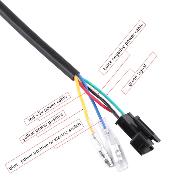
Throttle connectors.

https://ibb.co/ggSnrv

QS motor and kelly controller setup.

https://ibb.co/fVsLBv
 
Ya seems you have a few things not correct, on the kelly controller all the wires are numbered
Your throttle red goes to number 4 purple
Your throttle black goes to number 20 black
Your throttle green goes to number 3 green

Your motor halls connect to
Black number 21 to black
Purple number 5 to red
Blue 16 hall1
Green 17 hall2
Yellow 18 hall3

Then you need pink wire number 7 to touch the positive of the battery to let the motor spin
As long as your motor combo is correct it should all work

Good luck!
 
Yea, the Pink pwr connector turned on the kelly controller.
Finally figured it out, so the throttle yellow was suppose to go to the power to get the voltage display and the throttle blue to pink pwr 7 to send power to the kelly controller.

Thanks.
 
Awesome glad you figured it out. I just use a simple 3 wire throttle so wasnt sure which wires you were talking about. Happy ebiking!
 
I could use some help I am doing the same setup and have linked everything the same as you have but stuck what to link the yellow wire from the throttle too,
I was thinking the 5v power purple 4 but that's taken by the throttle wire already,
There is a 12v power wire 'number 11'? what power did you link it to in the end I know this is an old post but praying for a response as I don't want to get it wrong and overthinking it, first attempt e building
 
Thinking that you and the OP are both using this type throttle wiring setup that incorporates a switch of some type as well as throttle control...


MkVW2zd.jpg


The Yellow and Blue wires are typically high voltage connections.(not to be mixed with the low voltage hall sensor wiring!) With the yellow wire being the input voltage to the switch, and Blue wire being the "switched " leg of the switch. Which may also be connected to the input of an LED power level array.(battery state of charge lights)

As such the Yellow wire would connect to a Battery + or positive connection. And the Blue wire to pin #7 or the "ignition" or "key lock" circuit of the Kelly controller. As it requires full battery power at pin #7 to properly energize the controller's electronics.


Regards,
T.C.
 
so the yellow wire go's to the positive of the 2 lipos I have in series and the wire will cope with 45v? it won't blow anything?
everything else is wired up OK just seemed a tiny wire for the voltage and just had my worries thanks for your reply mate
 
Higher voltages can be a concern. But in this case the amperage involved is less than 100 milliamps... very low. This would be to power the LED charge level lights, and the controller circuit only. Thinking that the controller draw is 40mA.

Quite normal wiring for Ebike throttles, displays, and harnesses. Combining full battery voltages with 5vdc regulated controller electrical lines (supply, sense, and communications) with in in the same harness bundle. Always be wary when testing so as not to accidently short-out... :shock:
 
Back
Top