

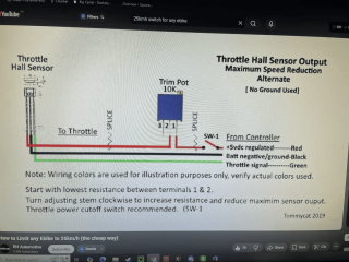
Hello, So in the first image i have a diagram of a ebike 3 wire variable throttle with a potentiometer wired on so you can limit the voltage that the throttle sends to the controller so it makes the motor slower. in the second image another person i found on youtube has wired a 3 prong switch so you can turn the circuit from limited throttle speed to unlimited (unmodifed) throttle speed. Now i bought this wireless circuit/remote setup online witch was about 3.5v in and out for the receiver circuit (third image. Now i want to wire in the wireless reciever instead of the manual switch, but i have no clue. if you could please draw a simple diagram on how this would work that would be very helpful. (the black and red wires on the receiver on the last pic is power in and the blue and white are power out)

-
Hello ES! We could use some help to get us past the finish line on building the new knowledgebase for the forum.
Can you donate? Please see our fundraising page. Thank you!
You are using an out of date browser. It may not display this or other websites correctly.
You should upgrade or use an alternative browser.
You should upgrade or use an alternative browser.
Need wiring help for ebike throttle speed limit with cut off remote
- Thread starter _Jo
- Start date


You are trying to replicate a SPDT (single pole double throw) switch with what is effectively a SPST (single pole single throw) switch. You might need 2 receivers, or relay, or a different module all together..Hello, So in the first image i have a diagram of a ebike 3 wire variable throttle with a potentiometer wired on so you can limit the voltage that the throttle sends to the controller so it makes the motor slower. in the second image another person i found on youtube has wired a 3 prong switch so you can turn the circuit from limited throttle speed to unlimited (unmodifed) throttle speed. Now i bought this wireless circuit/remote setup online witch was about 3.5v in and out for the receiver circuit (third image. Now i want to wire in the wireless reciever instead of the manual switch, but i have no clue. if you could please draw a simple diagram on how this would work that would be very helpful. (the black and red wires on the receiver on the last pic is power in and the blue and white are power out)
Like he said.
It's an interesting method of hiding a switch. I'd be concerned about failure to activate when needed.
Simpler and more reliable alternative way to hide a switch is to employ a reed switch, activated my magnet.
Even still, any speed-limiting switch is discoverable.
More foolproof would be a self-destruct switch. E.g. two pole switch between B+ and +5V. (Could repurpose your wireless SPST relay for that if you like)
Wipe out the 5V rail and the controller is cactus, with no way of proving it could exceed 25km/h
Sounds extreme, but if your bike is impounded they will find the switch and you'll lose the whole bike. Lesser evil is keeping the bike and replacing the controller.
Given the speed based control scheme you're proposing, your controller is presumably cheap.
It's an interesting method of hiding a switch. I'd be concerned about failure to activate when needed.
Simpler and more reliable alternative way to hide a switch is to employ a reed switch, activated my magnet.
Even still, any speed-limiting switch is discoverable.
More foolproof would be a self-destruct switch. E.g. two pole switch between B+ and +5V. (Could repurpose your wireless SPST relay for that if you like)
Wipe out the 5V rail and the controller is cactus, with no way of proving it could exceed 25km/h
Sounds extreme, but if your bike is impounded they will find the switch and you'll lose the whole bike. Lesser evil is keeping the bike and replacing the controller.
Given the speed based control scheme you're proposing, your controller is presumably cheap.

+1 for magnets  and hall sensors already come packaged for ebike use in the form of add on brake cut off sensors Pop a steel disk in the end of your handle bar grips and slide a small magnet to switch on?off as wanted..
to use your ebay module, provide the required 3.5v over the black(-) and red(+) wires. then use a multimeter to test the condition of the blue-and white wires.. im guessing pressing the button, or the remote button will connect/break blue to white which you could confirm/test with a multimeter in diode mode.
If confirmed to be the case, treat the blue and white wires as switch terminals
- Possible gotcha's 1) 5v logic level voltage may be too high for the module and blow something - perhaps consider a voltage divider or ldo solution to prevent this.
- stray 433mhz signals could turn on?off in awkward situations perhaps even dangerous ones?? ( unexpected full power when waiting at lights?? )
and hall sensors already come packaged for ebike use in the form of add on brake cut off sensors Pop a steel disk in the end of your handle bar grips and slide a small magnet to switch on?off as wanted.. to use your ebay module, provide the required 3.5v over the black(-) and red(+) wires. then use a multimeter to test the condition of the blue-and white wires.. im guessing pressing the button, or the remote button will connect/break blue to white which you could confirm/test with a multimeter in diode mode.
If confirmed to be the case, treat the blue and white wires as switch terminals
- Possible gotcha's 1) 5v logic level voltage may be too high for the module and blow something - perhaps consider a voltage divider or ldo solution to prevent this.
- stray 433mhz signals could turn on?off in awkward situations perhaps even dangerous ones?? ( unexpected full power when waiting at lights?? )
I have a bluetooth fardriver controller
Like he said.
It's an interesting method of hiding a switch. I'd be concerned about failure to activate when needed.
Simpler and more reliable alternative way to hide a switch is to employ a reed switch, activated my magnet.
Even still, any speed-limiting switch is discoverable.
More foolproof would be a self-destruct switch. E.g. two pole switch between B+ and +5V. (Could repurpose your wireless SPST relay for that if you like)
Wipe out the 5V rail and the controller is cactus, with no way of proving it could exceed 25km/h
Sounds extreme, but if your bike is impounded they will find the switch and you'll lose the whole bike. Lesser evil is keeping the bike and replacing the controller.
Given the speed based control scheme you're proposing, your controller is presumably cheap
i found this tutorial on tiktok where the guy had a 2 prong switch (underneath the potentiometer) wired up with his throttle on potentiometer, could i swap out the switch with the blue and white wires on my reciever? (btw i have fardriver, but i cant use the 3 speed because i have a surron sport/eco switch already wired on it)+1 for magnets
to use your ebay module, provide the required 3.5v over the black(-) and red(+) wires. then use a multimeter to test the condition of the blue-and white wires.. im guessing pressing the button, or the remote button will connect/break blue to white which you could confirm/test with a multimeter in diode mode.
If confirmed to be the case, treat the blue and white wires as switch terminals
- Possible gotcha's 1) 5v logic level voltage may be too high for the module and blow something - perhaps consider a voltage divider or ldo solution to prevent this.
- stray 433mhz signals could turn on?off in awkward situations perhaps even dangerous ones?? ( unexpected full power when waiting at lights?? )
Yes, once you have confirmed with the above outlined test that is how the module operates.
Not a legal expert, however i suspect that penalties for ridding a too fast bike would be inconsequential compared to penalties for modifying a bike to fool tests, so be mindful of this and research/consider the risks involved first.
post a query in a local legal forum at least..
Not a legal expert, however i suspect that penalties for ridding a too fast bike would be inconsequential compared to penalties for modifying a bike to fool tests, so be mindful of this and research/consider the risks involved first.
post a query in a local legal forum at least..
cheers mate thanks for the helpful info i will report back when i eventually get round to doing this. one last question can i source the power for the receiver from the actual throttle positive and negative, or should i use power from another power source?
Yes, once you have confirmed with the above outlined test that is how the module operates.
Not a legal expert, however i suspect that penalties for ridding a too fast bike would be inconsequential compared to penalties for modifying a bike to fool tests, so be mindful of this and research/consider the risks involved first.
post a query in a local legal forum at least..
Makes no difference where you tap 5V off, it's all on a common rail.
Surely it'd be better to utilise the fardriver's configurable rpm settings.
There's no hiding the mods you're making if your bike is autopsied after you flatten a pedestrian. And no longer any scope for plausible deniability. I.e. you'll get a more lenient sentence if you plead ignorance about any of this stuff and say you wanted to reduce the speed but couldn't figure out how.
Surely it'd be better to utilise the fardriver's configurable rpm settings.
There's no hiding the mods you're making if your bike is autopsied after you flatten a pedestrian. And no longer any scope for plausible deniability. I.e. you'll get a more lenient sentence if you plead ignorance about any of this stuff and say you wanted to reduce the speed but couldn't figure out how.
Could you please draw up a simple diagram of how i could wire up this whole thing?Makes no difference where you tap 5V off, it's all on a common rail.
Wireless relay came without instructions?
Ought to be simple enough that you can get by without a diagram.
It's safe to assume red and black supply power to the module, but best to test. Have you got a spare usb cable you can hack up? If so, strip it, find the positive and neutral (not necessarily red and black), label them as such, amd connect to the module's black and red wires. Perhaps a led lights up, perhaps it beeps, perhaps neither, but either way what you'll be looking for and need to verify is continuity between the blue and white wires when you push the remote control button. Does that make sense? Note that it'll be a latching relay.
Ought to be simple enough that you can get by without a diagram.
It's safe to assume red and black supply power to the module, but best to test. Have you got a spare usb cable you can hack up? If so, strip it, find the positive and neutral (not necessarily red and black), label them as such, amd connect to the module's black and red wires. Perhaps a led lights up, perhaps it beeps, perhaps neither, but either way what you'll be looking for and need to verify is continuity between the blue and white wires when you push the remote control button. Does that make sense? Note that it'll be a latching relay.

lnanek
🚴♂️ Mega poster
Switches are tough to explain away if the bike really does go to forensics, but something like a loop key, if removed when you get pulled over, just looks like an extra charging port. For a 5V signal you could even make a loop key out of a USB stick instead of the usual XT90 connector.
Similarly it's easy to have an extra automotive fuse holder wired in and change something based on if the fuse is present/removed/fully pressed in.
Potentiometers adjusted by screw driver might also not be seen as an intentional switch and more just tuning/manufacturing. Plenty of circuit boards have them. Kind of tough to quickly jam a Phillips in one and turn when you are pulling over, though.
Similarly it's easy to have an extra automotive fuse holder wired in and change something based on if the fuse is present/removed/fully pressed in.
Potentiometers adjusted by screw driver might also not be seen as an intentional switch and more just tuning/manufacturing. Plenty of circuit boards have them. Kind of tough to quickly jam a Phillips in one and turn when you are pulling over, though.
Last edited:
Replace your double throw switch with a relay that operates on 5v. Make it so when not powered, the attenuated throttle signal is the default. Use a reed switch as mentioned above, and a 5v source to trigger the relay for full throttle mode. Hide the reed switch in you bicycle seat. Now here’s what makes this a secure stealth trigger. Get magnetic underwear and position the magnets so full throttle mode is only triggered with your ass in a certain position on the seat. Chances are, the cops won’t have their own magnetic ass underwear, but there’s always a risk, since nothing is foolproof, but a very low risk. Maybe 20% or so. Sorry, can’t offer a diagram due to the magnetic shorts. Family friendly forum and all.
Similar threads

- Replies
- 12
- Views
- 1,336
- Replies
- 4
- Views
- 631
- Replies
- 7
- Views
- 690
- Replies
- 1
- Views
- 2,034
