nicd pack charger(finished)

dirty_d

10 kW
Joined
Jun 16, 2007
Messages
985
Location
Massachusetts
im thinking about building a nicd pack with those cheap sub-c cells on ebay, 30s5p. i dont want to have to use 5 chargers to change the damn thing, how about this circuit, that should work right. diodes to isolate each string. each string gets charged separately. the charge current will probably be about 1 amp for each string, so the fets wont have to dissipate too much heat 20W max i think, heatsinks and a fan should do the job. something else needs to be done to terminate charge in each string when it gets done, maybe an mcu to watch for the drop in voltage at the end of charge, maybe something crazy simple like a timer, i used to have a 15 minute nicd charger for my rc car, just a mechanical timer on the thing, cheaper is better!

the black box represents the nicd pack, just 2 series strings.

you adjust the pots for the current you want, its just constant current, so it will work with any voltage pack, as long as its less than 50, but not too much lower than 50 that the fets have to drop the voltage too much and dissipate too much heat.

i should have just used one pot, the currents wont be exactly the same, but close enough.
 

Attachments

  • charger.jpg
    153.1 KB · Views: 1,248
Instead of using diodes to isolate each series string, how about using a four pole double throw switch and reduce losses a bit? http://search.digikey.com/scripts/DkSearch/dksus.dll?Detail?name=360-1924-ND Is what I used. Batteries hook to the center terminals, controller gets all the "on" terminals, while each charger gets an "off" terminal. For more than four poles, gang several switches together with a bar like what 3-phase AC breakers use.

Marty

Edit: I've also seen NiCd chargers that use a thermal sensor to sense the end of charge. They either set a fixed temperature limit, or look for a given temperature rise in the pack. http://www.uoguelph.ca/~antoon/circ/auto-fan.html might work. Likely are plenty more plans hiding on the 'net.
 
yea that would work too, $12.00 though :shock:, if you get some low drop schottky diodes the losses shouldn't be too bad. i could use an avr to sense the voltage drop at end of charge, im not exactly sure how you would do that though, would you just store the highest voltage sensed so far, and if the next reading is X volts lower than that then that signifies the end of charge? or is it more complex than that?
 
you could just charge in standard mode, C/50 for 15 hours, the biggest problem i see though isn't the charge termination though, its the supply of 50V, transformers are expensive, so some type of switcher would be used, maybe just a simple buck converter.
 
dirty_d said:
yea that would work too, $12.00 though :shock:, if you get some low drop schottky diodes the losses shouldn't be too bad. i could use an avr to sense the voltage drop at end of charge, im not exactly sure how you would do that though, would you just store the highest voltage sensed so far, and if the next reading is X volts lower than that then that signifies the end of charge? or is it more complex than that?

Basically I think it's that simple. The more sophisticated chargers will average for a few cycles to cut down noise. They also have a lockout timer at the start of a charge so everything gets started reliably. They also often have to see the dip in voltage at the end of a charge for several seconds before they terminate.

Marty
 
ok thats simple enough, but there is still the problem of supplying the power, i think id need an isolation transformer to use as the inductor in the buck converter, but im not sure what i need, they seem to be pretty damn expensive too. im not sure what the peak volts of a 36V nicd pack is while charging, ive seen figures like 56V :shock:, ill settle for 3A split up between the series strings though.

could i get away with using a single inductor somehow? the output wouldn't be isolated so there would be a shock hazard to anything thats grounded right?
 
yea that would work, i might make a quick overnight charger, i saw that other thread with the unlimited cells charger, with the capacitor on the ac mains then to a full bridge rectifier, it outputs constant current based on the value of the capacitor, i think you could make it safer by puting something like a 60V zener diode across the output, so when there isnt a battery attached the voltage on the output wont go over 60V, then when you attack the pack, the voltage will drop down below 60V and just charge the pack. i cant seem to find any 6uF 200V non-polarized capacitors though. 6uF for 250mA, 15 hour charge for 2.4Ah cells.

heres the circuit if you dont know what im talking about http://endless-sphere.com/forums/download/file.php?id=11337.
 
Dirty_d,
I use two $10 24v/2amp radio shack transformers in series to power my 48v nicd charging circuit. With a bridge rectifier and capacitor from an old tv I get around 67v. Maybe combine a 24v and 12v transformer for less voltage?

I've been using a circuit very similar to yours but it interferes with my radio reception when it turns on :shock:
 
hey thats a good idea, 48V will be good, i think a fully charged 36V nicd pack is around 45V, i think each cell is 1.5V fully charged right?
 
actually i think what i will do is just use one 24V transformer and put a voltage doubler on the output, im just going to make this a 16 hour C/10 charger. the transformer is rated at 2.5A, so after the voltage doubler ill have 48V 1.25A, then ill have 5 strings of sub-cs each 2.4AH, so 1.25 / 5 = 250mA. works out perfectly.
 
Don't forget to multiply by 1.4 when going from AC to DC. My two 24v AC transformers are producing 67v DC.

http://www.hardingenergy.com/pdfs/NiMH_NiCd_Design.pdf

shows you may need almost 1.6v/ea to charge nicds.
I just got 80 tenergy sub-c's and so far they seem to be full at 1.43v/ea when charging. After I stop charging they drop to 1.30v. Maybe they need a few cycles to get going. Or maybe that's what you get for $1.30/ea!
 
Here's the constant current circuit I drew up based on thermistor circuits I've made. The one I've been using has different resistor values since I use what I hack off scrap equipment. The mofset and lm339 comparator are stocked at radio shack for a couple bucks. The mosfet heatsink gets hot as hell and like I said this thing must be sending out all sorts of bad radiation since I can't tune in my radio to my favorite station when it's on.
My intention is to add another charging leg along with a thermistor cut off comparator using the other 3 comparators on the lm339.
Charger.jpg
 
yea thats basically what i was going to do, the only thing i dont get is why the 5.1V source is going to the op-amps output and why it goes back to the + input through that feedback resistor/
 
the lm339 output sinks to ground so you need a pull-up resistor on the output.
With the feedback loop I was hoping to control the oscilation frequency so maybe it wouldn't be so electrically noisy or maybe the mosfet would run cooler. It's definately needed when comparators are used with relays to give hysterisis otherwise they switch on and off like crazy and fry the relay.
Everything I know came from looking at Bowden's circuits:
http://ourworld.compuserve.com/homepages/Bill_Bowden/page2.htm#therm.gif

Right now I'm powering my circuit with a 9v battery but I hope to figure out if a 5.1v zener could supply the power directly from the 67V.
 
what about just using a lm7805 or similar across the lower transformer output, that will be below the 35V max input to the 7805. i guess you would need to do your rectification differently though.
 
I tried using a separate bridge rectifier with the different transformer taps but I couldn't get it to have a common ground between the rectifiers.

I also want to try a different charger using a zener and resistor to regulate a tip42 power transistor. I'm not looking for anything real precise. Before I made the mosfet circuit, I would charge with just a 20 ohm resistor. So it started off fast but slowed to a trickle at the end. Definitely need a high temp shutoff circuit or keep it under c/10, the stories about exploding batteries are a bit scary :shock:
 
oops, the zener didn't work. I guess it needs only 50mA but at 62V my 1k resistor went up in a cloud of smoke :oops:
 
oh, you can also try this, get a darlington transistor, or a pair of transistors rated for above 62V, and your 5V zener, limit the current through the zener to whatever the zener current is supposed to be usually 5mA i think, so for 62V about a 12K resistance before the zener, take the darlington, or make a darlington out of the 2 separate transistors, and connect the collector to the 62V, and connect the base to the 5V from the zener, now the emitter will be your 5V output, the current it can provide depends on the transistors power dissipation, to supply 5V from 62V at 100mA, would require the transistor to dissipate (62 - 5) * 0.100 = 5.7W, the op-amp wont use anything near 100ma though, so id guess any to-92 transistors would work, or a darlington.

you need to take into account the voltage across the base-emitter about 0.7V i think so 5 + 1.4 for the zener, i used a 6.8V zener in the simulation.
 

Attachments

  • vreg.jpg
    35.4 KB · Views: 927
Cool, I'll try something like that. I need to read up on darlington transistors cuz I still don't understand how this circuit works. Couldn't you use a circuit like this as a battery charger?
What program are you using to do these circuits?
 
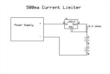
If you want a constant current source, you could just use a LM317 and a resistor. You can do the same thing with a LM7805 and a higher resistance.

Even simpler is just use light bulbs.

500ma Current Limiter.jpg
 
i like that, mush simpler than how i was going to do mine, with an op-amp current sense resistor and a fet for each series string. seems liek you will need a separate pot for each 317 to set the current limit though since they are all floating.

z_slo, i used multisim for the circuits
 
Yeah, much simpler! Thanks Fechter. I was thrown off by the LM317's 37v limit but it only sees the difference between the power supply and the batteries. A battery temperature sensing circuit or switch could turn off the adjustable leg.
 
Back
Top