Nucular Electronics owner's thread (setup infos, FW updates, links etc.)

John,

I did save the settling......I am completely oblivious to what went wrong?

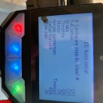
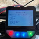
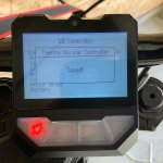
So when I tried the bike yesterday.....nothing would work right. I did save the programming the day before but for some reason the bike wouldn’t go. When I tried to go back through everything as I mentioned the angle correction kept timing out. The motor would freeze up and couldn’t be turned at all. Like the motor was trying to spin both ways at once? So I put the bike up. Today I tried again. Went through throttle, motor and then angle correction.....everything worked perfectly. Saved again, then rode around for about an hour. Completely clueless on what happened.

I did change to FOC instead of running on sine wave. Maybe that was the problem?

Tom
 

Attachments

  • 5013FEDB-E790-4640-8111-B0B3CD200EF4.jpeg
    5013FEDB-E790-4640-8111-B0B3CD200EF4.jpeg
    92.8 KB · Views: 1,437
  • 51AD0E4D-42B2-4E36-9BB6-A272D3DC5679.jpeg
    51AD0E4D-42B2-4E36-9BB6-A272D3DC5679.jpeg
    97.5 KB · Views: 1,437
  • 5479D250-897D-4741-B63D-0A4DA48E83E9.jpeg
    5479D250-897D-4741-B63D-0A4DA48E83E9.jpeg
    91.4 KB · Views: 1,437
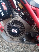
Sensorless FOC is planned sometime later. I hope this will come soon because I now run sensorless because off bad Hal signals. Problem is to start from zero speed. If the bike is rolling everthing is working fine.probleem eta2.jpg
 
I think that the engine parameters should be deleted because in sensorless mode, the engine should not be recognized.
 
I made a video presentation of my 12F with the commissioning, and the test with and without hall sensors.
You can choose the English subtitles. Tell me if you want another language.
[youtube]TZeuW8MINtM[/youtube]
 
24F Nucular with Sur Ron harness question. (it is not supplied with all the extra connectors for Cruise, Reverse, 3 way switch etc)

As delivered, is it only capable of two speeds, S1 and S2?

It almost seems that the documentation describes a process of assigning display Hotkeys with these extra functions. My Hotkey programming options don't offer any choice to select cruise, reverse, S3 etc.
 
Do not forget that you have the programming of the controller but also the programming of the display that you can customize. Originally the controller is supplied with the small jst connectors to add options to the back of the screen.
 
thoroughbred said:
My Hotkey programming options don't offer any choice to select cruise, reverse, S3 etc.

Strange, I have my hotkeys set up for s1,s2,s3 and reverse. Seems odd if that wouldn't be possible anymore. I dont use cruise, so I havent tried to program that. If it is a button to activate while riding, then I dont think I would want it on a hotkey anyway. I would rather use a button close to the grips, so it would be possible to activate without letting go of the handlebars.
I dont remember how it is done, but I was able to find out by reading the manual and looking in the menus.
 
j bjork said:
thoroughbred said:
My Hotkey programming options don't offer any choice to select cruise, reverse, S3 etc.

Strange, I have my hotkeys set up for s1,s2,s3 and reverse. Seems odd if that wouldn't be possible anymore. I dont use cruise, so I havent tried to program that. If it is a button to activate while riding, then I dont think I would want it on a hotkey anyway. I would rather use a button close to the grips, so it would be possible to activate without letting go of the handlebars.
I dont remember how it is done, but I was able to find out by reading the manual and looking in the menus.

The only "program hotkey" options given are for USB charging, and CAN1 through CAN9

I have found that you can set S1 or S2 to be reverse all the time. That leaves you with only a single speed and a reverse.

Did yours come with all the extra connectors coming out of the controller for all the optional input/output switches? The SUrron plug and play package doesnt have those.
 
No, as standard there were no connectors on the controller. I ordered that extra, but didnt notice that there were 2 extra I had to order. So I only got the inputs, not the pwm outputs.
I dont have my controller connected at the moment, so I cant check. But I think you should be able to use the hotkeys for just about anything. Maybe it is a different menu you have to change something in first?
 
You have to go to the "controller parameters", and to" I / O configurations". There you can set the function "CAN port 1 to CAN port 16". You can give a function to each of them. For example" CAN port 4 = RV". Then you go to the "On board computer" settings and in" Buttoms setup " and there you set the "HOT Key 1 function" to" CAN buttom 4". When you keep pressing button 1 the reverse gear will start. You can set each button this way.
 
I made a video to explain you can activate the English translation
[youtube]7KvbdhWueUQ[/youtube]
 
I asked this in the Main controller thread as well, so sorry for the double post

Just have a couple of questions on hooking up a Bake Light through port P1.
I have the brake switch connected to IO8 on the display and I set port P1 to Spec. and PWM to Stop-Light.
Should I be able to see, using port state, that I have a output signal on P1 when I use the brakes?
Also do I have to access P1 from the controller or can I assign it to an spare output on the Display?

thanks Eddie
 
I'm making a small hall sensor board and magnet ring to mount to the shaft of my LMX motor. I can get perfectly even spacing on the hall sensor and magnet positions but I will have to estimate the position with respect to the actual magnets on the rotor. So the hall timing will end up slightly advanced or retarded based on this position. I think I can get them within a few degrees of the positions of the rotor magnets.

Will this present a problem?
Will the auto setup compensate for this?

The answer to this will determine how much adjustment I build into this setup.

My goal is to get the halls completely away from the windings.

Here is the plan so far. I have some Neodymium 45 Arc shaped magnets on the way to go in this plastic part that will clamp to the shaft.
Mag Pickup.png

If anyone sees any reason why this wont work please let me know. I'm far from an expert on these things.
 
DanGT86 said:
Will this present a problem?
Will the auto setup compensate for this?
I did something similar and it works well with Nucular, so a few degree + or - should be no problem. Nice design :thumb:

https://endless-sphere.com/forums/viewtopic.php?f=30&t=91144&start=25
The answer to this will determine how much adjustment I build into this setup.
If you place the Halls near the area where the windings enter the stator and magnets aligned with the rotor, then you should really not need much room for adjustment.
Here is the plan so far. I have some Neodymium 45 Arc shaped magnets on the way to go in this plastic part

If you use arc shaped magnets, then you need half of them with N and half with S on facing outside, otherwise it will not work.
 
Thanks Maddin88. Your design was actually what got me thinking about this.

I had heard of people adjusting the timing of the halls to get an efficiency bump. I assumed that is what the Nucular is doing during the auto setup.

As for the design, the original plan was to mill it from Delrin Acetal plastic. I have concerns that the split clamping feature might lead to the screws coming loose over time because of the heat cycles. I would rather use aluminum so I can use loctite in the threads and make them tighter. This seems like it would stay in place better. Locktite doesnt really stick to Acetal plastic.

My concern with aluminum is that the magnets will induce fields and confuse the halls. Its the gaps between the magnets that bothers me. So there are still a few unknowns here.

I think I'll make the first version so it mounts to the shaft externally so I can try some different things without having to break the motor case apart every time.

Its frustrating to have to add magnets to a motor that already has magnets but I have been hearing people complain about the hall signals from these LMX motors for years. I'd like to have some confidence in the eventual fix.

Here are the magnets. Half come with N facing out and half with S facing out.
https://supermagnetman.com/search?type=product&q=m5005
 
A guy in France made a very simple system with a disc that has holes and an optical sensor. A second adjustable disc makes it possible to obstruct more or less the oval holes with fine tuning. The advantage is simplicity and no disturbances due to magnetic fields.
This made it possible to transform a car alternator into an engine with a rotor position sensor, just as hall sensors would.
Sa vidéo est ici :
https://youtu.be/WkbbDcLWDdQ
 
That optical solution is very clever. Years ago Burtie was selling a similar optical solution for small high RPM RC motors. Optical will be my plan B.
https://endless-sphere.com/forums/viewtopic.php?t=31961

Does anyone know if the hall sensors are attracted to the magnets? Specifically how solidly do I need to mount the halls. Can they just be soldered to a PCB or do I need to be captive in a bracket to keep from moving?
 
Hi. I have nucular in my ebike. It has freewheel which allow wheel rotate freely without rotating motor.
I am going to change setup so that no freewheel. It means that motor will generate power when no acceleration.
Can this nucular handle this kind of situation? If it can, which parameters need to be activated? Is there some risk of damaging unit?
Please give some advices
-Mikko
 
Yes it even works very well my controller generates 10% energy when slowing down. That is to say that for 100wh used it produces 10wh which makes a consumption of 90wh.
It sets the "active braking parameter" in the" control menu" to stop the motor at 0 speed. In the "advanced control mode", don't forget to set the speed limit. at 0% acceleration". This allows speed to be limited when the accelerator is fully released. You can also find this parameter in "Configuring the throttle and brake voltage range". Look at https://docs.nucular.tech/doku.php?id=en:start
This is not a problem if your bms is suitable for charging through the discharge port.
 
A couple more questions...
In battery setup, dV value is for telling the stat keeper that the battery is fully charged? If battery voltage is within 1.5 volts of the max supply voltage from charger, display resets statistics for a fully charged battery?

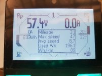
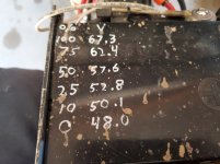
I told the display that my battery capacity is 2.8kwh. I have burned through 2kwh and the bar graph is counting down.20201211_130902.jpg

According to these figures I found for the sur ron battery, my state of charge should be 50% rather than 30%. I guess I'll keep draining it and see what voltage I have at the end of 2.8kwh, maybe my cells behave differently than the surron panasonics
20201211_132358.jpg

Lastly, in quick data display, it looks like battery consumption is always shown per kilometer even though mine is set per mile. The calculation is correct but the label is wrong
 
Back
Top