Open source BMS for 48V to 400V lithium-ion battery pack

ENNOID said:
The BOM for LTC6811 is completed and the order on digikey is ready . I can provide a link to share my basket on github ennoid-BMS.

The new LTC6813 IC are still scarse right now on mouser and digikey, and I will wait before working on the board. Anyway for testing LTC6811 will be cheaper and easier.

There is still the BOM for Master if you want to help and the associated digikey or mouser basket to build.

Yeah please share the BOM on github for the Master and LTC6811. What can I help with for the Master? I'd be happy to give the build a try for testing if that's what you need.
 
Hello ENNOID !

What kind of Current sensor you will use for monitoring the current and what will be the balancing current dissipated by the resistors on the PCB ? For larger cells which are charged faster is good to have 1W/or more/ resistors.
Everything looks very good designed, and the idea for scalable stacking is great! May be only the connectors which don't have "lock" pin can be replaced to guarantee proper connection in vibrational environment.
I have one 18S battery pack , I can assemble one Mainboard with LTC6813 IC to give it a try.

BR
 
Hi,

Right now, the current sensor is external and not mounted on master PCB. The actual current sensor is an isolated shunt copper bar mounted on a tiny PCB which is equipped with an amc1303 amplifier & isolated power. Available in the github repository. On master, there is a connector with 3.3V output to power an inputs to receive the signal for the external current sensor. No heavy currents from the battery are circulating on the master PCB. I might do a PCB shield for master in the future which would carry high currents, switches & sensors.

I received last week all PCB (Master, Slave-LTC6811, PSU & current sensor) & I'm still populating them. BOM are in repository. I haven't ordered an LTC6813 PCB because the IC has a lead time of approx. 20 weeks. :cry:

For the connectors, yeah I agree that they are not great. I just trowed something to make a working prototype, but I think I will change that. There are so many connectors available, it is sometimes hard to find the proper one. There might be some connectors with lock compatible in the actual 2.54mm pin format.

What kind of connector would be the best? Any suggestions, part numbers?
 
Hi ENNOID,

I agree that external current sensor is better solution for two reasons- You galvanicaly separate the BMS from HV part , and you avoid heating of main PCB due high currents. I take a look on isolated shunt sensor. It's not bad decision at all ? What is the accuracy of this solution ? Now on the market have many options /LEM , Tamura/ using hall effect , with accuracy 0.8-1% with current consumption 10-15mA in rated current /6-1000A / and standartised power supply 5V. They offer simplicity and many options for the primary bar hole form and dimension/can be mount directly on cable without cutting and crimping/ . And last , they can be find very easy on the market.

I still didn't understand what is the balancing dissipating current which is possible with the board ? I see surface mounted resistors , so it's not more than 1W I guess? For quick charged batteries , I'm not sure is it enough or not ? For 100Ah cell charged for 4hours , I should measure the circulating currents to share some values....

About the LTC6813 , I have search for it before couple of weeks , and yes...the delivery date back on stock is after more than a month. Obviously is a sucessfull IC !

Connectors are specific topic , because the decision shall be based and depends from mounting of the PCB. One is sure, the screw type is universal and guarantee fast and reliable contact. I will search for other variants and will quote them in the topic.

last, congratulations for the good work! :thumb:
 
I still didn't understand what is the balancing dissipating current which is possible with the board ? I see surface mounted resistors , so it's not more than 1W I guess? For quick charged batteries , I'm not sure is it enough or not ? For 100Ah cell charged for 4hours , I should measure the circulating currents to share some values....

Yeah, if more than 1W is needed per cell for balancing, I think it would be easy with kicad on slave to just add other 1W 2512 format resistors in parallel, space is not a problem right now on slave board.

I agree that external current sensor is better solution for two reasons- You galvanicaly separate the BMS from HV part , and you avoid heating of main PCB due high currents. I take a look on isolated shunt sensor. It's not bad decision at all ? What is the accuracy of this solution ? Now on the market have many options /LEM , Tamura/ using hall effect , with accuracy 0.8-1% with current consumption 10-15mA in rated current /6-1000A / and standartised power supply 5V. They offer simplicity and many options for the primary bar hole form and dimension/can be mount directly on cable without cutting and crimping/ . And last , they can be find very easy on the market.

I decided to use a custom homemade current sensor, but again It would be easy to adapt master to use any kind of 3.3V current sensor. Very small changes would be required. Other solution would be to use the actual master board as is and to remove/bypass the delta sigma buffer stage and it should work fine. Then just connect the sensor to the 4 pin connector on master.
 
ENNOID,
Very few connectors are in 2.54mm format, most of them smaller or much bigger. I'd suggest looking into the microlock series from molex, I've found then to be compact, very reliable and have lots of different options.
Also, I abandoned my original design with the LTC 6813 because we needed it much sooner than stock would arrive(early April). My new LTC6811 design that has been approved by Analog engineers and ordered for testing next week is on the same github

demony
The LTC6813 is not popular by any means. It is plagued with manufacturing issues and delays and resulted in the demo board being out of stock, preproduction samples being faulty (which were what I was using and having troubles with) and that's why theyve taken nearly a year after it's release to claim it is ready for production.

To address the sufficiency of a 1W resistor, the answer unfortunately is, it depends. A brand new set of cells are generally pretty balanced and can actually be used with little to no balancing, but an older set, especially a set scavenged from a scrapped electric car for example, will be more imbalanced and require much more balancing. How do you find out how long that balancing will take? You calculate the difference in current capacity between the highest and lowest cell and divide by your dissipation current. A small 10Ah pack with a pretty standard imbalance of 2% has a difference of 0.2Ah. a dissipation current of 0.5A will give a balancing time of 24mins. A larger 20Ah pack like the one I'm designing, or a 100Ah pack that you referred to, will need much more dissipation ability if you want faster charges, you could always just deal with a longer charger or buy better binned cells with lower variations or address any number of other variables

Chai
 
c10yas,

Molex Micro-lock is a very nice connector and would be a good replacement. I just don't have the crimpers to insert terminals on the cables. The OEM crimpers are very expensive as well, something like 500$... Do you know if PA-20 crimpers would work with the terminals? I normally buy very cheap 3 x 2.54 or 4 x 2.54 ribbon cables already assembled with headers on ebay which avoid me to deal with cable terminals.

I also used ribbon cable with press-fit header in the past and it was a very easy process to do good connections. I just don't like having to spend hours playing with cable assembly.
 
IDT connectors should not be used for this kind of thing because in my admittedly limited experience I have not come across any with much in the ways of a voltage rating or positive retention. I'm designing my pack for an electric race car and have to meet stringent rules and obviously follow general safe practices.
The microfit series from molex is rated for even higher voltages (which is what I'm using) at the expense of being bulky, but I suspect microlocks are sufficient for a 48V pack.
Pick a crimp and a wire size and then the crimping tool can be any generic one advertised to work for that gauge of wire. These crimps aren't anything special, amazon has tonnes of $20-30 crimpers that would be just fine.

All of this of course is at the expense of time. Preassembled IDT connectors are convenient and easy to use but have the aforementioned disadvantage of not meeting any standard of safety when it comes to a HV battery pack imo. Maybe you could use them for testing since you already seem to have a lot of them, but I'd strongly advise properly voltage rated connectors with positive retention for any actual use case. The positive retention would be especially necessary on something like a skateboard or quadcopter pack that will see a lot of vibration

EDIT:
I just checked what PA-20 crimpers are, if they are the right gauge they seem to be fine. But last I checked 22AWG which is the size that microlocks use, is 0.5mm2, and the PA-20 crimper I see on Amazon only goes down to 1.6mm2.
 
Ennoid, this project looks AWESOME! It's a huge gap in the market right now for a reasonably priced master/slave BMS. I'm using repurposed Chevy Volt packs for my RV and right now I have a choice between $$$ or going for cheap chinese un-networked BMS's.

I can't see purchase information on your website, have you figured that out yet? I'm running 3p12s with 8 packs...

Thanks!
 
Hi,

I'm still working on the firmware and waiting for a GUI tool update V0.30 from diebiems. The harware is ready, but the firmware is still limited right now with the slave LTC6811/LTC6804 and temperature ADC128. The guys from diebiems are working on the code quite heavily at this moment and my coding skills are still limited.

If there was any good coders on this forum that would like to help us for the firmware code, that would be great.

@justinpirie: I'm not sure to understand, do you mean that you are running 8 pack of 3p12s in serie?Any more details about this 96s pack?
 
Hi Ennoid.
Any news about the new firmware and gui tool?
I'm looking to build your bords and test them.
It looks like a very promissing project
 
I'll update both gui & firmware on github soon.

Functionnal now with last code updates on my side with tweeked parameters.

I'll start selling bare & assembled PCB very soon on my website...
 
I'm using an elcon/tc charger right now and it seems to be good enough and cheap:

http://evcomponents.com/customized-chargers/elcon-tc-hk-h-1800w-charger.html

Even without CAN communication for voltage regulation, it charges properly, but I'm still planning to support CAN communication with this charger...
 
I received several private messages during the last month about the project status and I think it is time to share some details.

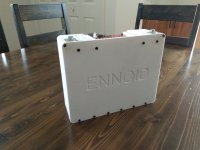
First, I had to create my own battery modules for testing my BMS slave boards. I have been able to fit 120 x 18650 cells 12S10P in a 3Dprinted plastic case with Fire retardant ABS filament on my prusa MKII which gives me around 44.4V/module 50.4V when fully charged with approx. 1.5kWh capacity/module. I wanted a battery pack that is integrated with my ENNOID-BMS slave board and I ended up with battery modules that can be connected in parallel & series with other modules with quick connectors and minimal effort. For assembling the modules, all cells connections are done from one side & signals for cells voltages & temperatures sensors are routed toward the Slave BMS through the top PCB. This allows bottom cooling plate. For communication with others modules & master BMS board, only a twisted wire pair cable connection is required. I tested so far with 4 modules in series which is approx 200V.

Here is a rendering I made which shows the battery module concept with integrated Ennoid-BMS slave:
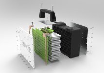
pack exploded crop.jpg

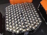
Here is a picture of a single battery module after putting the cells into the platic case (prototype without top handle):
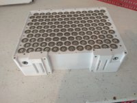
IMG_20190802_145049.jpg

With ENNOID-BMS slave board sitting at the front before cell connection & without top cover:
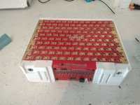
IMG_20190802_142938.jpg

Once completed:
IMG_20190810_143543.jpg

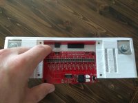
Slave-BMS assembly:
IMG_20190810_144705.jpg

Here is the wiring diagram of the actual test bench:
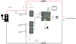
Wiring.png

And finally the bench test with only one module that I later connected to a VESC 6 & small BLDC. It works! (the end goal is not to spin a small BLDC but a several KW motor):
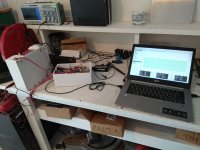
IMG_20190806_155046.jpg

Here is a screenshot of ENNOID-BMS tool with 2 modules in series 24S approx. 100V:
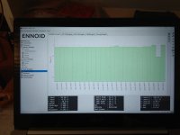
IMG_20190810_151109.jpg

So far everything works except the 8 temperature reading/modules when several modules are connected together (driver for the ADC128 is still in the work). Small adjustment are still needed for current & voltage sensing, but overall I'm satisfied.

The operation of the whole BMS is now possible:
- Charging
- Balancing
- Temperature monitoring ( Still some issues with ADC128 but slave & master temp monitoring are working)
- Voltages monitoring for load & pack
- Current monitoring for charge & discharge
- Cells voltages monitoring with single or several modules in series
-Precharge, discharge, charge with EV200 type contactors, up to 500A continuous
- several protections (over-voltage, under-voltage, over-temp, under-temp, over-current etc.)
- BMS tool and adjustable parameters (everything is working, but the interface will be simplified for Ennoid-BMS (DiebieMS HiAmp shield parameters not needed.


I will also create a small video in the future, which should explain all the details of the BMS & associated Battery pack & "Penthouse box".

The goal of the penthouse box is to create an easy plug & play setup for ENNOID-BMS. It has all the stuff packed inside for a complete ENNOID-BMS. It contains master BMS board with contactors, current sensor, power cabling, output & input cables & 12V 5A power supply .

Here is the wiring diagram for a complete system with the "penthouse box" & ENNOID modules :
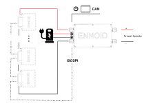
wiring.png

I will soon start to sell standalone assembled BMS board, "penthouse boxes" & battery modules on my website for the ones interested.

On my side, I'm planning to build an atv equipped with my penthouse box & my battery modules.

Of course, the whole thing is open source!
 
This is a very nicely integrated design.

Can you provide any more detail about the interconnections? Does the large red circuit board provide the load current paths for the batteries or only the balance voltages and balancing current paths?
 
Hi,

The large top red PCB has many purpose, but is not meant to carry the load current path. Maybe it carries the load current only for very short distances at the junctions with the busbars on both ends.

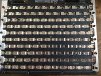
The large red PCB main purpose is to avoid using many wires to connect the slave BMS board to all cells voltage for balancing & for connecting to all 8 temperature sensors. At first it sounds like a strange idea, but I can now assemble a pack easily without any wire mess & with less chances of mistakes. It also looks great imo.

All cells are connected + & - on this PCB & the main current path is carried over the interconnections between cells. Interconnections between cells are secured on the top PCB and at the same time connect all parallel cells together with the slave BMS board. Temperature sensors are mounted directly onto the top PCB (SMD temp sensors). Connection to parallel modules cell voltage is also done from a connector on the main top PCB. I have been inspired from alta motors battery packs actually, but made some change to make the design more flexible.

See alta motor pack below:
s1200_IMG_2787.jpg

My design is quite similar, but the monitoring IC LTC6811 is mounted on the separate BMS-Slave board. Right now I'm spotwelding cells manually, but I'm looking for using a CNC machine with an ultrasonic aluminium fuse wire like Tesla & alta packs in the future. The design of the slots on the top PCB allow both options right now (spotwelding & fuse wiring)

Here is an early version done with spotwelding (the actual version looks a bit better now):
unfinished module.jpg
 
Those photos are very helpful and I can see that this connection scheme is unique. Most e-bike battery packs I see have the cells "flipped" for each of the parallel groups and have spot welded connections on both sides of the battery pack.

This design and the Alta pack have all cells in the same physical orientation and connect to the rim of the cell to provide the negative connection. What advantages do you see in this design and are there other packs using this configuration?
 
tesla is doing like that as well on model 3.
easier to assemble an easier to automate.

There is also no fiddling with wires/cable harness in this configuration when building the module.

Also it leaves the bottom section open for a cooling plate with thermal paste...
 
@DRDRS: Here is a well described article on the topic:

https://insideevs.com/news/342519/tesla-model-3-battery-current-collector-radically-different-design/
 
Hi Ennoid

What is the plan for the wireless chip on your master board?
Is it to connect wireless to the bms?
In the bom it state that it's a 900mhz wireless transreciver
 
Well, I asked Dany Bokma from diebiems if there was any plan to make wireless works (no code at all). He told me that It was initially planned to add wireless communication to the initial Diebiems , but NRF bluetooth on vesc6 is now standard and he sees no need to have wireless on both bms & motor controlller. Also metr app already works with diebiems. It should work as well with my ENNOID-BMS, both use the same code. I removed the wireless module in the latest schematics I havent updated the BOM for a while. It would be nice to implement an nrf wireless module + code in the future though...
 
Hi Ennoid.
Thanks for your reply...
Are you planing to update gerber files and bom for the pcb's on github ?
Just noticed that you have removed the gerber files from github.
 
Back
Top