flippy
1 MW
- Joined
- Aug 12, 2015
- Messages
- 2,351
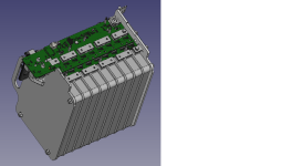
very nice.
just noticed 1 tiny thing: the micro usb.
that connector is is only one that is to the side, i would recommend changing it to a type B vertical connector. its much more durable for EV use and then you can even dunk the board in coating or a closed bottom housing as all the connctors are at the top reducing and spaced needed as you dont have to dick around with trying to get a tiny connector into a hard to reach location when mounted in a vehicle or electronics box, a vertical type B is much more practical in that sense.
do you plan on having either a strip of a few leds of a breakout connector for a led bar that can light up to display basic errors like current or voltage errors or com link faults so you can do fast disanogsing without having to plug in every time?

")