opensource 3d printable electronic shifting?

Reserved for doodle.
Buffering.

So, made a doodle.
Suffice to say, this is very much a australopithecus afarensis to what's to come. However, it does show what can be done with mechanical engineering software such as FreeCAD by a hooplehead as yours truly, while doing the laundry. I cheated a bit and I must add; its food for thought and not carved in stone and such and such. Now, FreeCAD is free, download it and give it a whirl.

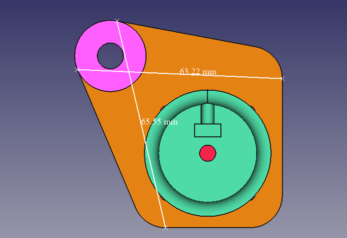
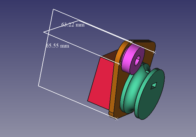
I used the dimensions from the first hit of a NEMA 14 stepper (5Ncm), which aught to be way more power than needed. (if anyone has the specs/dimensions of something more hm.. reasonable, I'm all ears.)

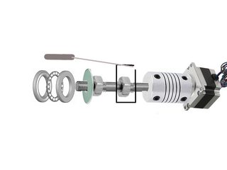
The pink part is a V-grooved 608 bearing, with a M8 washer. (cheated a bit there)
The turquoise part is a 3dprinted "spool" for the wire, fastened through the hole.
The orange part is the plate that's going to be fastened to the frame.
The red part is the NEMA14 stepper.

(Download the attached file and have a look in FreeCAD! Sorry had to zip it, because phpBB-forum settings)
View attachment Bluetooth Open Source Shifting System v.0.01.7z

If anyone would like to scribble down the relevant measurements of a frame, whatever part specs that could be used, and/or any ideas by all means, that would be helpful! The more info, the more we all got to ponder/work with!

I licensed it as GPLv3(as a statement of intent) AND as a homage to those wholesome titans of developers over at Flexible OpenSource firmware for TongSheng TSDZ2 mid drive motor!

qPEbbg4.png

3qrUY5X.png
 
Also - though I don't have the right background to do the ME work on this project. I do have the right background to do the software/ee ;). So if anyone gets there mechanicals worked out I'm happy to make a cpu go and have it talk to our SW102 for the control/user interface/ebike integration.
 
Also e3s, I think that size sounds fine because it will still nicely mount on a chanstay (or whatever)
 
@mittkondo really cool! What do you think of e3s's idea of a long threaded shaft (about 6 cm) with a gear one one end and then that gear meshing with your stepper? On the threaded shaft could ride a little slider that pulls the cable. The reason I think that idea is appealing is it would keep the derailer in gear even if the motor is off (if the gear ratios were correct?). Also the gear ratio would allow selecting a smallish motor (because running many revolutions on the motor to move the slider on the shaft a short distance is probably good for other reasons - resolution mainly).
 
Possibly interesting? https://dingsmotionusa.com/nema-11-linear-actuators

Or this very inexpensive linear servo which was included in my Prusa 3D printer. To my non ME fingers it seems to have SUPER high resistance to movement when the power is off. And it has plenty of resolution for small Z movements.

A similar pitch threaded rod attached to a smaller stepper (NEMA 11? NEMA 8? size) might work?

NEMA 17 (too big) example: https://www.aliexpress.com/item/32977907686.html?spm=a2g0o.productlist.0.0.2b1a36favxJInx&algo_pvid=d4da6191-0da9-4fe7-b9aa-253108fbe70a&algo_expid=d4da6191-0da9-4fe7-b9aa-253108fbe70a-19&btsid=8518b27f-e570-4f26-ab57-46ed37348cb0&ws_ab_test=searchweb0_0,searchweb201602_1,searchweb201603_60

Various NEMA 11 examples: https://www.aliexpress.com/wholesale?catId=0&initiative_id=SB_20190915185737&origin=y&SearchText=motor+screw+nema11&switch_new_app=y

In particular: https://www.aliexpress.com/item/33039511645.html?spm=a2g0o.productlist.0.0.c51976afyiyOpk&algo_pvid=78252f6d-fab6-41ae-9652-73349bdd3cfc&algo_expid=78252f6d-fab6-41ae-9652-73349bdd3cfc-11&btsid=3e8fd4cf-bc44-4d93-a1fb-3037ceb535a0&ws_ab_test=searchweb0_0,searchweb201602_1,searchweb201603_60

Or this with a 3d printed cable attachment fitted to the sliding white plastic bit: https://www.aliexpress.com/item/33040826145.html?spm=a2g0o.productlist.0.0.227164ee2b10NF&algo_pvid=d36b7e15-98fc-432c-8e6c-ad956fddf101&algo_expid=d36b7e15-98fc-432c-8e6c-ad956fddf101-4&btsid=963a30d5-7456-4581-bce6-02797acc7f6a&ws_ab_test=searchweb0_0,searchweb201602_1,searchweb201603_60

And if using a stepper, no need to have an encoder or a limit switch if the driver does current sensing (so at start we could find the zero position and then move to the calibrated gear positions we learned and stored in eeprom)

5VbCtMq.jpg
 
Hi geeksville, I'm very happy to see this project! I think that a nema8 is good choice

https://it.aliexpress.com/item/33022432482.html?spm=a2g0o.productlist.0.0.315d477baV5rO7&algo_pvid=b4dd4c28-c95e-4215-a757-f12d817c423d&algo_expid=b4dd4c28-c95e-4215-a757-f12d817c423d-24&btsid=d5b5b17a-1d7f-42c2-9247-ca5aef376747&ws_ab_test=searchweb0_0,searchweb201602_10,searchweb201603_52

It is more than 2 times stronger than necessary, a guarantee of functioning over time!
It is quite compact, its 20x20mm design allows us with a 3d printed shell to have an actuator of maximum 25x25x100mm, just insert a bearing at the end of the shaft, and lock the control cable to the threaded ring nut!

As you said the limit switch is not needed because at the start the logic should bring the derailleur on the longest gear (then releasing the cable until the end of the screw), then return to the position saved before switching off.

Have you already thought about the driver of the motor / board to use? I think it would be better not to insert it inside the actuator, and maybe insert it in an external box.
Finally, we can apply a ring at the end of the command screw, to be able to rotate the stepper in case of failure and change even the gear!
We also need to find a compact bt remote for shifting gear, or maybe we can use a wired keys to controller (more reliable, no battery, no bluetooth needed).

I hope to see this project grow along with the sw102 on our ebike!
Thanks You
 
For now I'm searching a stepper motor that has a constant torque curve, not less than 8 N.cm
Nema8 is a bad choice because it has 4 N.cm. Too low. I'm asking if someone has a balance to measure how many kg are needed to change the gear pulling the cable... I apologized 5 kg but I'm not sure.
 
E3s I know nothing about such things but: what about a smaller motor but then a gear on the motor meshing with a gear on the leadscrew? It seems to me we could happily ratio those gears so that many turns of the motor would move a small number of turns on the leadscrew?
 
The problem is this: to change the gear in a certain amount of time there's a need to have a fixed power. If you have a motor with 1000rpm with a gear 10:1 that changes the gear in a second, it will consume the same power of a motor with 100rpm and changes. The gear in a second. So there are already little motors with a gearbox and low rpm, but it will take seconds to change the gear. An acceptable time is 1 second. Nema8 maybe is ok with a minimal gear ratio but for a few cm It does not worth it. Nema 14, 1.5A, apologizing 5 kg of force is ok. If the force to pull the cable is higher nema17 goes well. Take care of the torque curve.
 
btw - e3s, Once I select the type of (cheap) rear derailleur I'm using on my next bike I might buy one as a bench test. Then to get your measurement would it be sufficient for me to hang a weight from the cable and see when I have enough weight to get full travel?
 
not the full travel but only to change a gear (or also two gears,), pull 5 mm of the cable to change the gear with a sram or the half for shimano.
It is sufficient to see the weight to pull from the second to the first gear. It's the hardest to pull. Obviously with the chain not without it.


my project is this one in the photo. Sorry for the bad quality but I can't use now a better software to design it.

WZlgpemm.jpg


from left to right : thrust bearing, washer, nut, nut with a 3d printed cube to pull the cable, joint, stepper motor.
the cube must be printed in half with the shape of the nut inside and on the top the housing for the cable. it must have 4 points on the sides to fit it with the other side or gluing it or putting 4 screws. My pc is slow and I can't draw it to explain better how to build it. for those who do not have a 3d printer is fine a square washer with the grinder, you make room to fit the wire and welded to the nut. Or simplier making it with the wood following the same instruction for the 3d printed one. a guide shaft can be taken into account but I do not think it is necessary. the joint is not needed if the stepper motor has the shaft but its thread density is not so common and the nut is not easy available. prons is that the pulling force is on the left and the stepper motor does not suffer. It has a limited load capacity, not knowing how many kg are needed to pull the cable this solution is safer. Maybe if the force is low the direction to pull the cable can be inverted and the thrust bearing can be replaced with a normal bearing. the housing can be 3d printed but before I need to have on hand all pieces and now I haven't them. The measures will be more precise. First I'll use the wood to make the housing, then it can be 3d printed with the correct measures.
 
Maybe you guys can have a github repository, I created this one: https://github.com/OpenSource-EBike-firmware/OS_Electronic_Shifting -- geeksvile has access and I can give access to the other interested developers.

Would be great if you could use the git for the 3D files, instructions, etc.
 
Good idea.
For now I'm looking for buying the joint and the thrust bearing, it could be useful to buy different stepper motor to verify the limit of the torque required. This varies also from the friction of the shaft. The friction is not also the same. Example bronze threaded rod has lower frictio, if it's lubed or not... Depends also from the gear ratio. I think that shimano derailleur need more power. I haven't it, if there is someone that can test the force of the cable to shift the gears...
 
For the stepper motor driver I suggest drv8825 it's cheap, 80 cents.
 
You can see approximate motor and 'gearing' parameters on this vid:
https://www.youtube.com/watch?v=uuCiaa6zUoM

Using a 'linear worm screw' is the best idea because it has passive and has nearly indefinite 'holding torque', so no need to keep the system powered unless actually shifting. It also has built in significant reduction - you need many revolutions to move the 'slider' required amount.
Problem is (and I'm sure that's why all x-shifter style systems out there are are 1x) front shifters require much more cable tension to shift, so it will be either slow and/or require a larger motor and generally beefier construction.

An other, and more significant problem is making it user-friendly. There are ton of shifters our there, with vastly different pull rations and some of them even have a nonlinear leverage curve as I understand.
Not really a problem for a DIYer though - you can spend some time 'ironing out the bugs' by manually constructing a 'shifting table' for each system you require.

I am not much of an MC, but I find this such a system very interesting because I have recumbent, and recumbents have unique problems with cockpit space and cable routing.
 
Nice find BalorNG!

Came here to post something I stumbled upon lurking and raking the net about odrive for a corexy machine.

Anyho, found these type of Linear Actuators, which very well could be the droids we are looking for as they are conveniently packaged.

Never mind the fancy remote & etc in this particular link above, would be lovely to use a bafang sw102 specifically for this purpose.

However, as I suppose these are straight up dc motors with endstops(?), and not encoders(?), we need encoders(!(?)). Maybe something like this or some magnetic encoder such as this. I am not well versed in the arts of containing magic smoke in this regard.
 
Actually, I design such an e-Shifter for my Enduro Ebike frame, using a servo coupled on a lead screw. This design is pulling on the derailleur cable and no load on servo motor after it is on the chosen gear. Lead Screw design are best as you don't need to modify the derailleur, as the force it take to make the servo motor turn when it is stop is plentiful to keep the lead screw from turning by the derailleur pull spring.

You can see my design on this post:
https://endless-sphere.com/forums/viewtopic.php?f=28&t=103714

Anyone here good in helping with Arduino coding, I want to add auto shift down with speed decrease to my current design.

Cheers
Dan
 
Back
Top