rscamp
⚡ Regular
I was going to add this to the end of the CYC Photon Gen 2 thread but that thread is already huge! Even describing this will require several posts.
Some 3D printed parts have been designed, prototyped and fitted to a 2008 vintage TRICE QNT trike to facilitate a Photon Gen 2 retrofit. Last year the trike was fitted with the Gen 1. I am seeking reduced thermal power limiting with the Gen 2 for climbing the Niagara Escarpment. Even though this is an installation for a specific trike, I think there are a few ideas that could be applied to any bike install and even more that could be applied to other trikes. 3D models (e.g. STEP) of any or all of the items designed can be supplied on request.
Anti-Rotation Plate
A "mid drive" (crank drive) like the Photon is mounted to the BB on the front of a trike. The reaction torque of a crank drive can be resisted by the derailleur post on a trike similar to on a diamond frame but the angle of this post locates the motor above the boom and with more overhanging mass. It is much better in my opinion to employ an anti-rotation device to locate the motor on the underside. This frees up the derailleur post for other things (e.g. lighting) and improves stability by lowering the centre of gravity and improving front-rear balance a bit.
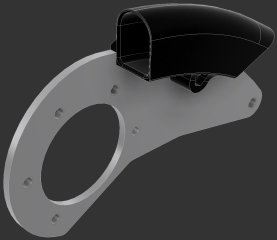
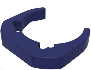
Unlike most other parts referenced here, the anti-rotation plate is profile cut aluminum plate. However, for test fitting a prototype 3D printed version is perfectly adequate. 3D printing is simply awesome for prototyping in general. The first image shows the Gen 2 mid drive with the Gen 1 anti-rotation plate and an orange coloured 3D printed prototype of the Gen 2 anti-rotation plate. The two motors are similar enough that the Gen 1 plate would actually work. It interferes slightly with a radius in the enclosure casting but this could be addressed with some filing. By making it longer the screw that will affix it to a T-Cycle idler mount will be accessible outside the radius of the CYC 50T chainring and chain guard required on a trike with a 20" rear wheel.

Accommodating Photon Chainline
The Photon is made to be adaptable to many BB widths and as such it has a relatively large minimum Q-factor. The chain line established by the chain ring is therefore farther from the trike centerline than the stock idler positioning was designed to accommodate. Here are the numbers copied from my design notes:
CHAINLINE:
This indicates that offsetting the idler about 10mm farther from the trike centerline will provide a better chain line. But fitting a spacer to increase the offset immediately uncovered a problem that led to multiple prototypes with incremental improvements (Kaizen!). The interference with the steering rod end is shown in the second image.

No problem. I'll profile cut a modified design for the idler bracket out of aluminum. First a 3D printed prototype:
But this part doesn't have to be tremendously strong. Maybe it can be made with ABS plastic if the bending stresses are addressed with ribbing:
This looks like it will work fine. However, the part ended up going through further iterations to also secure shift cables for a Rohloff IGH. Here is the "final" version. The CYC 1-4 cable can be seen behind the idler mount plate.
The next post will show a mount designed for the Intuition Display.
Some 3D printed parts have been designed, prototyped and fitted to a 2008 vintage TRICE QNT trike to facilitate a Photon Gen 2 retrofit. Last year the trike was fitted with the Gen 1. I am seeking reduced thermal power limiting with the Gen 2 for climbing the Niagara Escarpment. Even though this is an installation for a specific trike, I think there are a few ideas that could be applied to any bike install and even more that could be applied to other trikes. 3D models (e.g. STEP) of any or all of the items designed can be supplied on request.
Anti-Rotation Plate
A "mid drive" (crank drive) like the Photon is mounted to the BB on the front of a trike. The reaction torque of a crank drive can be resisted by the derailleur post on a trike similar to on a diamond frame but the angle of this post locates the motor above the boom and with more overhanging mass. It is much better in my opinion to employ an anti-rotation device to locate the motor on the underside. This frees up the derailleur post for other things (e.g. lighting) and improves stability by lowering the centre of gravity and improving front-rear balance a bit.
Unlike most other parts referenced here, the anti-rotation plate is profile cut aluminum plate. However, for test fitting a prototype 3D printed version is perfectly adequate. 3D printing is simply awesome for prototyping in general. The first image shows the Gen 2 mid drive with the Gen 1 anti-rotation plate and an orange coloured 3D printed prototype of the Gen 2 anti-rotation plate. The two motors are similar enough that the Gen 1 plate would actually work. It interferes slightly with a radius in the enclosure casting but this could be addressed with some filing. By making it longer the screw that will affix it to a T-Cycle idler mount will be accessible outside the radius of the CYC 50T chainring and chain guard required on a trike with a 20" rear wheel.
Accommodating Photon Chainline
The Photon is made to be adaptable to many BB widths and as such it has a relatively large minimum Q-factor. The chain line established by the chain ring is therefore farther from the trike centerline than the stock idler positioning was designed to accommodate. Here are the numbers copied from my design notes:
CHAINLINE:
| Photon Gen 2 | Rohloff Sprocket | T-Cycle Idler |
| ~50mm with specified spacers | 57mm + 6.5mm ICE offset = 63.5mm | 46mm measured as is 50mm – 63.5mm target 57mm mean |
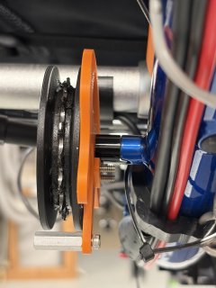
This indicates that offsetting the idler about 10mm farther from the trike centerline will provide a better chain line. But fitting a spacer to increase the offset immediately uncovered a problem that led to multiple prototypes with incremental improvements (Kaizen!). The interference with the steering rod end is shown in the second image.
No problem. I'll profile cut a modified design for the idler bracket out of aluminum. First a 3D printed prototype:
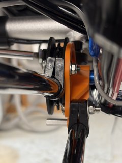
But this part doesn't have to be tremendously strong. Maybe it can be made with ABS plastic if the bending stresses are addressed with ribbing:
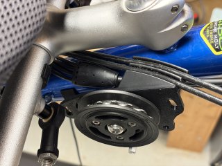
This looks like it will work fine. However, the part ended up going through further iterations to also secure shift cables for a Rohloff IGH. Here is the "final" version. The CYC 1-4 cable can be seen behind the idler mount plate.
The next post will show a mount designed for the Intuition Display.