Problem with the ping battery.

cana77

1 W
Joined
Feb 26, 2010
Messages
59
I originally got around 72volts from the battery when I tested it with a multi meter . Now I am only getting 72v right after its charged but right away it shoots down to 55v. It is not enough to turn on the controller. I use a
48-72v 35amp Crystalite controller and a Crystalite 5304 rear hub motor in a mountain bike.

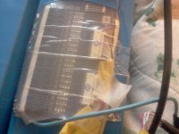
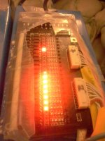
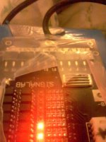
I have included a picture of the battery after it is charged. All the leds lighten up except 4 which is what it usually did before.
It was working great just till the other day.
Is there anything you could suggest.


Thanks!


Chad
 
first thing is to put it on the charger and measure each cell voltage and list them.

those top four cells have a separate 4 pin plug (the black one) that may be loose and preventing it from balancing too. but if it was loose then the BMS would shut off.

we gotta know how it balances in order to guess. so measure each cell at the sense wire plug on the BMS.

put the black on the B- spot and the red on the first pin on the back of the sense wire plug. that is #1, measure each adjacent pin up to the top of the pack.

is it a 24S pack? or 16S? i did not think ping made a 24S so your 72V DC measurement may have been in error. the BMS should not allow the 16S to charge up to 72V DC.
 
Thanks for your reply,
Im not sure if its a 24s or 16s pack i dont know what that is :) sorry :) all i know is its a 60V 20AH V2.5 LiFePO4 Battery Pack split it in 2 packs.
can i tell if i could the small wires on the bms?
here is some pics close up so u can tell me where i have to measure each cells votage.
 

Attachments

  • IMG_20130408_164140.jpg
    IMG_20130408_164140.jpg
    89.9 KB · Views: 1,260
  • IMG_20130408_164213.jpg
    IMG_20130408_164213.jpg
    182.7 KB · Views: 1,260
  • IMG_20130408_164323.jpg
    IMG_20130408_164323.jpg
    392.5 KB · Views: 1,260
Have you contacted Mr Ping about the problem? ..What's he doing to help you?
 
ok, 72V from a 20S lifepo4 is normal. should charge up to 74V usually. dropping to 55V immediately is bad. how long do you leave it charging?

if you can measure the voltage on adjacent pins on those sense wire cables it will give you the drained back voltage on each cell. but eventually you wanna measure on the pcb while charging to verify the BMS is working properly. so you should consider cutting the plastic off the BMS. use scissors and cut down the middle of the back side to get it off. then you can put it back on later, but just measure the plug for now. that should say a lot.
 
ok i cut the plastic off the bms and got the measurenments starting from the first pin
the batterery was not connected to the charger when i did the measurements but i just recently charged it.
3.33
6.67
10.01
13.34
16.92
20.5
24.1
27.6
31.2
34.8
37.1
40.7
44.3
47.9
51.5
55.1
58.7
62.3
65.9
69.5

so its showing more when I check it that way then I check from the other connector its only showing 53.5 from the discharge cable i think its called.
Thanks for your help :)
 
ok, i thought it was the top of the pack that was low.

your first four cells supply the circuit current to the BMS that drives the mosfets and control circuitry. if you leave the pack uncharged for long periods then those first four cell lose their charge and the pack is unbalanced.

if you leave it on the charger you will see that the charger is green when one of the other cells hits the 3.9V level and turns off the charging mosfet.

so that is why you wanna measure while charging. also measure just the two adjacent pins on the back of that plug on the pcb so you are measuring the individual cells. extracting the cell voltage from the series is harder and not as accurate because you need to use the 20V scale on your digital voltmeter.

but for now just leave it charging, it may take days unless you can use a big power resistor and drain off the charge in the top 16 cells as you charge.

do you have old tvs or other junk with those big cement resistors? or you can use a light bulb across those top 16 cells to drain them down to force the pack to balance faster.

but start charging while you speculate. leave it charging until the leds come on. they will unless the first four cells have been seriously damaged by over discharge.
 
ok I tested again with it charging and the green light was on the charger.
here are the measurments i got
3.34
6.7
10.5
13.4
17.06
20.7
24.5
28.3
32
35.7
38.2
41.9
45.5
49.3
53.2
57.1
60.8
64.5
68.3
72

ok how do u measure each cell individually? which pins i can take a better pic of the bms if u want.
 
did the maths in excel for you

off the charger

3.33
3.34
3.34
3.33
3.58
3.58
3.6
3.5
3.6
3.6
2.3----bad cell?
3.6
3.6
3.6
3.6
3.6
3.6
3.6
3.6
3.6


on the charger

3.34
3.36
3.8
2.9 (not sure what's going on here?)
3.66
3.64
3.8
3.8
3.7
3.7
2.5-----same cell as above
3.7
3.6
3.8
3.9
3.9
3.7
3.7
3.8
3.7


looks like a bad cell to me, I put ----- next to it

not sure how the ping bms handles charge, you might need to try to charge it separately?
 
put the probe tips right into the solder at the base of where the pins go into the pcb. put the black probe on the lower pin and red probe on the upper pin. use 20V scale and read to .01V.

the tops of each of the cells is connected to each of those pins in series. when you measure between adjacent pins then you are measuring the voltage across that cell.

it looks like it is #8 that is shutting off your charger. you can look to see if there is one cell reading the 2.5V he mentioned too.

you need to find something to drain down the top of the pack to make it charge. if you have a junk tv they have big 47-60 ohm power resistors in the back where the AC cord plugs in. or you can use a light bulb by taking a table lamp, incandescent, and use some jumpers with alligator clips (harbor freight) and connect each side of the AC cord for the lamp to the top of cell #4 and to the top of cell #20 (the red one).

you wanna use a resistor at least 40 ohms to keep the current under 1.5A. so if you use a light bulb use a 25-40W bulb max. power resistor is easiest to use. you can even use your ammeter to measure the current draining off those top 16 cells. just put it in series with the resistor as you drain the cells down using the alligator clips to hold the probes. use the 10A scale on your ammeter.
 
Knighty wrote: not sure how the ping bms handles charge, you might need to try to charge it separately?
That's what Ping will tell you too use an RC charger or a cellphone charger and pull those 2 cells voltages up. I had the same problem once and it worked. :D
 
Hey i cant figure out how to measure each indvidual cell. is there a webpage with pictures online somewhere i could learn from?

one other question why is it when i check the voltage when its plugged in to the charger i get 72.8v from the discharge cable,and when its unplug from the charger i get 55.6v from the discharge cable?
also when i measured the the pins on the bms without it connected tp the charger i got 69.5v
 
if cell #11 does measure 2.5V and that led is on then that shunt transistor is damaged for sure.

so measure it first and if it is down to 2.5V then connect the resistor from the top of #11 to the top of #20 to drain down that section and then when those cells get down to the 3V level you can go drain the other cells from top of #4 to the top of #10 down to 3V and then the first 4 last down to 3V all the while charging that low #11 up.it is completely discharged and may even be damaged bad..

so the idea is to get all the other cells as low as that cell so they can charge up together. but the led lit at 2.5v is a dead giveaway.
 
to check each cells voltage individually, check the first one

then when you move the red probe along to test the next cell, move the black probe along too where the red probe just was


how long did you leave it on charge for ? have you tried a good long charge ?
 
ok ill try to check each cells like that on the bms.
I left it charging for a few hours maybe i can leave it longer but i dont think its doing anything because the green light is on the charger and i dont hear the fan going. when i hook up the battery and the charger to the bike and i turn the switch the back wheel goes for a sec and the charger comes on but then it shuts off.
 
Ok i think i did it right here are the measurements i got for each cell off the charger
3.34
3.34
3.34
3.34
3.65
3.66
3.69
3.79
3.66
3.68
2.34
3.66
3.66
3.69
3.88
3.80
3.66
3.71
3.69
3.77
 
here are each cells voltage with the charger connected.

3.35
3.35
3.35
3.35
3.68
3.71
3.76
3.92
3.71
3.72
2.25
3.68
3.70
3.77
4.03
3.92
3.71
3.81
3.77
3.88
 
ok, you gotta drain down those sections that are high to get the sections that are low pulled up.

you can try using a cell phone charger but everyone seems to over charge them and destroy them then. but obviously #11 was drained down to zero by the shunt transistor. just now getting charged.

that led is on, right?
 
ok how would discharge them with a cell phone charger? or could i just charge #11 cell?
# 11 cell led is on but its getting dimmer as the charger is plugged in.
 
since the led is on we know that the shunt transistor for #11 is turned on. so it is draining 60mA of current out of the cell constantly.

do you have an idea of what the BMS does and why those leds are now all turned on?

the cell that measures 2.5V is too low in voltage for that shunt transistor to be turned on and allowing current to drain out through the led. either the comparator that drives the shunt transistor is dead or the shunt transistor itself is dead or both as it often is.

this happens because this is a two part pack and when there is a break in the connection between the two packs, then all the current flows through the BMS comparator and shunt transistor on that cell next to the open cable.

do you have resistors laying around or any tools or know someone who does?

if you look at the BMS, can you see the shunt transistor at the top of each row of shunt resistors? you can see the two legs on top, and the trace running off to the sense wire plug?
 
the bms as far as i understand is supposed to balance the battery.
no i dont have any resistors. what kind of tools would i need? i dont know anyone that knows about electronics that much.
I included 2 closer picture of the bms.

how would i go about using a usb phone charger to charge that one cell? would that fix it? or could i just use a lamp like u said and put the red wire on one of the cell legs and the black negative wire on the bms where it says b-?
what if i didnt use the bms at all just to get the bike working.

thanks for your help :)
 

Attachments

  • IMG_20130408_220845.jpg
    IMG_20130408_220845.jpg
    227.7 KB · Views: 1,174
  • IMG_20130408_221006.jpg
    IMG_20130408_221006.jpg
    150.2 KB · Views: 1,174
you should have cut the plastic along the back side like i laid out. then you could have folded it back over the BMS again later.

you have a bad shunt transistor on #11. you need to charge that cell up. i explained how to hook up a resistor. the B- is the bottom of the first four so you would connect between B- and the top of #4, but first you have to drain down those really high sections #12-20 and #5-10. if you don't have alligator clips and jumper wires you should go buy some. sometimes you can buy voltmeters on sale at harbor freight. i just got three more for $2 each but i burn them up a lot.

until we know how bad off that cell is it doesn't matter because if that cell is dead your whole battery is dead.

you have to get it charged up and then see how fast it loses charge after that, your bulk charger can charge up the low cells if you drain the charge off the high cells. it seems straightforward. if you have a single cell charger then use it, or even a 14V charger for #1-4 but the problem is how dead is #11.
 
Have you contacted Mr. Ping?

He is very helpful and generous with his time.

I have similar a problem with one of his batteries I bought back in Spring 09.

He is sending a new BSM and a single cell charger. (for a price)

The one bad/low cell I have, is not as low as yours, 3.3 vdc.

.One of the BMS lights staying on after charging and pulling down the voltage in that cell. Hopefully, this low cell can be saved.
 
Back
Top