So I've been trying to decipher the serial protocol of the ASI controllers, to find a way to quickly reprogram entire profiles of parameters by a hardware switch instead of just the speed/max power available by the native street/race modes through digital inputs. For example, change phase amps and min/max field weakening for an 'efficiency' profile at the saturation limit and a 'wheelie' profile to drop jaws

As well, I'd prefer to have my torque sensor and throttle as separate inputs on the BAC8000 and use its assist profiles to disable/adjust the torque sensor or control max power natively, rather than externally through a cycle-analyst and shunt. I tried *many* port sniffing applications but none worked for various reasons-- driver, x32 architecture, unmentioned trial limitations.
So I asked Martin about it. He provided this very helpful attached document on the MODBUS implementation used by ASI controllers. With this information, after checking the slave ID in BacDoor (1 for this serial input) I was able to read or edit parameters using only a PuTTy serial terminal. Turns out this is quite straightforward and I'll be using these findings to develop a python-based display for ASI controllers to run on a Raspberry Pi.
For example, to read the field weakening value I send the following command (in hex):
01 is the slave ID. 03 represents the command, read register. 00 81 is the hex for address 129 (register 128!). 00 01 represents the number of registers from 129 to be polled-- just this one. D4 22 is a "CRC" code, kind of like a two-byte hash generated from all the previous bytes of the request and calculated independently on each device, compared to ensure the data was properly transmitted.
As you can see, it is really quite easy to program these values. I have since discovered a nice program
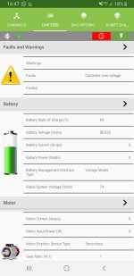
Modbus Master that makes it easy to experiment with commands and log the actual serial data between the PC and controller. Conveniently, many of the parameters are logically grouped. With one command, you can poll controller temperature, vehicle speed, motor temperature, motor current, motor RPM, motor speed, battery voltage, battery current, battery SOC, and battery power by reading address 259 and the following 10 registers:
So to adjust field weakening to 0% on my controller, the value is 0 and the command 10 to write holding register 128 (address 129) results in the follow line:
Code:
01 10 00 81 00 01 02 00 00 b8 41
To adjust to 50% field weakening, the value is 2048 and the resulting hex command is:
Code:
01 10 00 81 00 01 02 08 00 bf 81
In both cases, in accordance with the attached protocol, the controller sends the following to confirm successful receipt of the command at that register:
I've now decided a simple profile switch would be too easy. There is great support for MODBUS on a variety of devices... I want to make my own display. Arduino is too slow to write to a display one pixel at a time, so I think Raspberry Pi is the answer. It's a bit like using a sledgehammer on an ant but cost is comparable to Arduino and it will guarantee exceptional responsiveness on the display, and can be used for many other purposes e.g. dashcam logging, interfacing with other onboard devices like a lowjack or relays for accessories, running Android/navigation, Diablo2, whatever. :lol:
So, I'm developing an open-source Pi-based display for ASI controllers. I'll do just one screen with key stats... maaaybe a 2nd screen with interesting trip stats. Main screen will show speed, power, Ah from logged current/time and from that Wh/mi trip average and "instantaneous" rolling average, battery voltage with a most sag in last x seconds indicator/value, motor temperature with indicator when foldback initiates, controller temperature, buttons to increment and display current assist profile, and a few buttons to switch preset configuration profiles based on exported .xml... and a button to arm my GeogramOne lowjack, engage antitheft, display a keypad and wait for a PIN to unlock.


 ):
):