Proper Wiring of the CA/EBrake to 116 Controller (BLP7245)?

GCinDC

100 MW
Joined
Jan 23, 2009
Messages
4,261
Location
Washington, DC
New controller issues...

I've just swapped my 846 infineon controller with a 116, bought directly from Keywin/ecrazyman, in an attempt to get higher regen. (for braking, not nec for charging...)

So first, I've performed the following mods on the 116 out of the box from Keywin:

-> jumped BK/GND (acutally put them on a switch)
-> removed R12 and soldered in 1K ohm resistor
-> soldered programming header to board (and programmed board with these settings)
-> added power switch, or attempted to.... The power lead connector had three wires: two thick +/GND wires and a thin red + wire attached to Vcc-1.
I assumed the thin + wire was for a switch so I wired it like my 846 controller is wired: with a switch on the thin + wire from Vcc before it enters the + powerpole terminal. (as in the diagram below). Not sure what mate there should have been for this on the battery side...

So, the issues:

__ 1. When I turn on the switch (which I ran to the handlebar), the CA Voltage reads a steady 82V for 15-45 seconds, and THEN it shoots up to 93V and oscillates there, within a volt or two. Somewhat disconcerting, having lipos & all... but obviously there's no change in battery voltage. This is w/ bike at standstill, no throttle at all. I've tried timing it, but timing isn't consistent. Seems to occur sooner after depressing eBrake...
View attachment 1
__ 2. The eBrake lever, when depressed, causes the CA to display only backlighting, no more characters, and have no effect on braking. The eBrake line, (YEL/BLK from controller) isn't wired to EBS, as on 846 controller. Here are some shots from top (L) and bottom (R). Is this correct??
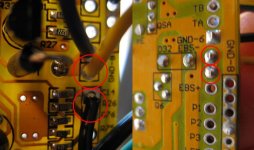
Fullscreen capture 1242010 12749 PM.jpg
Any suggestions!?

My build thread here. Issues mentioned in last post, p. 5.

Thanks
 
Greg,

My experience with the thin red wire is that this is the "ignition" wire that is switched from positive battery input. I usually connect it to the red power wire into the controller when I crimp on an Anderson connector. This makes it easier for me when I disconnect the battery to take it off the bike to charge at work.

Dave
 
dbaker said:
...the "ignition" wire that is switched from positive battery input. I usually connect it to the red power wire into the controller when I crimp on an Anderson connector.

Hmm, Let's try this.

I wired the thin red from the controller as follows:

controller ------ thin red ---(ig Switch)------ (crimped to anderson below )
controller ------ THICK RED ------------------ [anderson][anderson] ----------- + terminal on battery
controller ------ THICK BLK ------------------ [anderson][anderson] ----------- BLK terminal on battery

What do you have?:

controller ------ thin red --------- [anderson][anderson]----------- ignition switch? ---+ terminal on battery???
controller ------ THICK RED ------ [anderson][anderson]----------- + terminal on battery
controller ------ THICK BLK ------ [anderson][anderson]----------- BLK terminal on battery
 
Both GND connections for the CA need to connect to the same place at the bottom (GND) of the shunt. Move these first and then see what voltage your CA reads.

Your EBS- wire photo is a little confusing, the red circles on the left don't match up to the red circles on the right.
The top two wire (black and yellow) are connected to the same place (EBS-), connecting either of these to GND should cut power to the motor and activate regen.
I would expect to see the bottom two wires connected to the standard two pin connector Keywin uses for EBS- but where does the top black wire in that photo go?
 
Mike1 said:
Both GND connections for the CA need to connect to the same place at the bottom (GND) of the shunt. Move these first and then see what voltage your CA reads.

On a whim, I decided to do this last night... (It all felt like deja vu to my woes w/ CA and 846 board. )

I removed both GND wires and attached them to extensions to the bottom of shunt.

I also cut the EBS wire, as is on my 846 board.

Result: At turn on, CA displays, clear characters, steady voltage @ say 81V. Fifteen seconds later however, the display starts to flicker, gets lighter, and Voltage rises to 93V and hovers there.

Squeezing ebrake however no longer causes characters to disappear.

Also, I removed my 'ignition switch' wire that runs to the handlebar and jumped the switch on the Vcc line at the controller. The display was instantly more clear! Made me think my connectors are crap. (CA pigtails). Or that the switch line is wired incorrectly. Or that the switch line is not supposed to be on a long wire, that it'd prefer to be close to the controller.

Your EBS- wire photo is a little confusing, the red circles on the left don't match up to the red circles on the right.
The top two wire (black and yellow) are connected to the same place (EBS-), connecting either of these to GND should cut power to the motor and activate regen.
I would expect to see the bottom two wires connected to the standard two pin connector Keywin uses for EBS- but where does the top black wire in that photo go?

I think you're right: the circles on the right don't match up. Maybe moot point? The 6th wire in the CA pinout, the blue - I clipped that. Regen's working great too!

It's definitely stronger, as is the controller! 45A, yeehoo! Anyway, from 30mph, I get up to -7.5A, and still haven't config'd the shunt those seems to max at 44A, so is probably close. I think I'll keep regen as is. Nice strong drag, Not skidding or anything, lets up around 8mph for a light coast, but I can activate it again w/ ebrake.

So, where am I at?

- I've still got a flakey Voltage reading, after 15-30seconds, occasional flickering, and possibly crappy connections.
- I really want to have if not ON/OFF switch at handle bar, then a kill switch. Is my switch wiring messed up? it's identical to my 846 controller
- I need to get the spark down when i plug in the batts, my powerpoles aren't going to last long w/ that "ZAAAAAPP!". time to look into that resistor mod?
- I could solder up the shunt to get higher current/regen
- I've got 12 new 4110 FETS fresh from methods: Should I replace Keywins? What would be the result of that upgrade?

Thanks!
 
So the throttle over-ride wire was soldered into one of the EBS- pads? That's the old way of wiring the CA for speed and current limiting, we usually wire into the throttle line now.

It still sounds like a GND wire problem, the CA backlight should never vary in brightness even with large changes in battery voltage. The length of the switch or ignition wire shouldn't matter as long as the connections are good, my ignition wire is at least 5 feet long, maybe more.

The 4110 fets will increase efficiency by staying cooler due to a lower turned on resistance, the less power wasted in heat the more power you will get to your motor. If you decide to beef up the board and increase the current limit then swapping in those new fets is a really good idea.
 
I don't know if the blue wire was the throttle override wire. I see no label on the back or front next to that wire. I just noticed that it was clipped on my 846 CA connector and decided to try it clipped too. The difference:

BEFORE: hitting ebrake caused screen to go blank (too brightly backlit!)
AFTER: hitting ebrake caused no change in screen contrast

The green is attached near the halls, so perhaps it's getting a signal off one of those?

I should add, and this happened routinely w/ CA on 846 board: at startup, it frequently displays something like: >>>>on;oFf<<< though I've never been able to read it well...

It definitely flickers tho. Will test jumping connections closer to controller, eliminating connector variable.

-g
 
Update:

I plugged in the freshly charged pack this morning. <SPARK!>

Turned on handlebar switch (perfect location for thumb, below throttle). Flash: "CYCLE ANALYST 2.0"
Then: "83.2V 0.00 MPH... etc"

Display clear as a bell, no variation after 1 minute.

Hopped on the bike, rode it to work;
- Voltage never varied.
- Display never flickered.
:mrgreen:

This is similar to how my last CA issues were resolved. Jiggering around connections and then one day it works!

I can only assume that artificial intelligence is built into the infineon chip: It must take several cycles for it to learn bike configuration and then automatically adjust. I can only imagine what sensitive data it is secretly transmitting to Vancouver... :lol:
 
Does the speed display correctly as well?

You're going to have to do something about that spark.
 
Recommendations about the Spark? I remember reading something about an inline resistor/capacitor on the switch line??

Speedometer actually seems right too! IT never varied, like voltage, only faded out w/ entire display. Odd, considering that was my previous issue w/ the infineon.

I confess however, I gotta be careful glancing at the CA nowadays. It goes so fast!

Crikey, the thing wants to do wheelies all the time! I'm psyched I went w/ this controller (Thanks for the suggestion).

Max amps on WOT from standstill go up just over 40A. Rshunt still set to 3.122 ohms (for old 846 controller). Seems about right, but might be higher! Might need to calibrate.
 
To stop the spark you need to use a pre-charge resistor. I would suggest connecting a resistor between two powerpoles, then when you first plug your battery in you connect it in series with one of the wires. After 20 seconds or so you remove the resistor and plug it in direct. You need to add up the total of the big capacitors on the main power bus so I can work out what resistor you want.
 
GCinDC said:
PS. Mike, how is your ignition switch wired?
Have you done anything about the spark?

My ignition wire goes from the output of the main breaker up to the front of the bike, through a switch and back to the controller.
I've got the pre-charge resistor ready to fit across the main breaker with a switch but haven't got round to fitting it yet as I rarely disconnect power from the controller.
 
Mike1 said:
To stop the spark you need to use a pre-charge resistor. I would suggest connecting a resistor between two powerpoles, then when you first plug your battery in you connect it in series with one of the wires. After 20 seconds or so you remove the resistor and plug it in direct. You need to add up the total of the big capacitors on the main power bus so I can work out what resistor you want.

like this?
a1726156-108-Resistors.jpg

from: http://www.rcgroups.com/forums/attachment.php?attachmentid=1726156 ?
 
I was suggesting a piece you put in between temporarily but that would work just the same.
I'll try to find out what the total of the big caps is on that controller. How long do you want to wait for it to pre-charge? The shorter the time the bigger (physically) the resistor gets.
 
Well I was thinking I don't even have a resistor that small - that's I'd have to parallel some to get them down below 100 ohms. My resistors are scrawny though. 1/4 watt? Would those work?

I know that my biggest [EDIT: capacitors, not resistors!] on the controller are 100v 1000uf. Not sure about the others.
 
Not sure where they got those resistor values from, way too low.

The 50ohm at the initial 84 volts would be dissipating 84*84/50 = 141 watts. Even lowering this due to the short timescale you would probably want a 50 watt resistor which is pretty big physically.

Assuming 4000uF total capacitance it would take 1 second to reach 99.3 percent of full charge.

A more sensible value would be something like a 490 ohm.
This would give you 99.3 percent charge after 10 seconds and you could get away with a 5 watt resistor.
You probably wouldn't wait the full 10 seconds, it would reach 66 percent charge after 2 seconds which might be enough to eliminate the spark.
 
Mike1 said:
My ignition wire goes from the output of the main breaker up to the front of the bike, through a switch and back to the controller.

so do your power connections look like this (w/ slash indicating thin red coming out of breaker on thick + line)?

(BATT + BREAKER(fuse) /--- (+ thin red) ------- handlebar switch ----[connector][connector]-----controller
(BATT + BREAKER(fuse)/----- (+ THICK red) -----------------------------[connector][connector]----- controller
(BATT) --------------------------(GND)--------------------------------------[connector][connector]----- controller
 
GCinDC said:
Mike1 said:
My ignition wire goes from the output of the main breaker up to the front of the bike, through a switch and back to the controller.

so do your power connections look like this (w/ slash indicating thin red coming out of breaker on thick + line)?

(BATT + BREAKER(fuse) /--- (+ thin red) ------- handlebar switch ----[connector][connector]-----controller
(BATT + BREAKER(fuse)/----- (+ THICK red) -----------------------------[connector][connector]----- controller
(BATT) --------------------------(GND)--------------------------------------[connector][connector]----- controller


Correct.
 
Mike1 said:
A more sensible value would be something like a 490 ohm. This would give you 99.3 percent charge after 10 seconds and you could get away with a 5 watt resistor. You probably wouldn't wait the full 10 seconds, it would reach 66 percent charge after 2 seconds which might be enough to eliminate the spark.

Okay, not a lot of options at the store. I picked up:

2 x 5 watt .47 Ohm
1 x 20 watt 8 Ohm (5% tolerance)

They're huge. Will they work? One 5 watt .47 ohm okay?
 
You need much higher ohm values than that.

The 8 ohm would be 84 x 84 / 8 = 800 watts, so that resistor would burn as you plugged it in.
The .47 ohm would pull the max current your batteries could supply so would be the same as you have now, big spark and a burnt resistor.

You need to find something in the 100's of ohms range. Something around 500 would be ideal.
I could send you one if you can wait for postage, I'm in the UK. The one's I have are well over spec and so pretty big.
 
Mike1 said:
....that resistor would burn as you plugged it in....Something around 500 would be ideal.

Glad I didn't try it. And I saved the receipt. :D

I'll hunt online for one close by. But thanks for the offer.

500 ohm 5 watts...

Thanks!
 
Back
Top