Amperry417
10 W
- Joined
- Aug 24, 2021
- Messages
- 67
Hey Guys,
I'm somewhat new to EV and building my first custom battery for my electric scooter, Vsett 10+. I am looking for any suggestions and advice regarding a few things. I would really super appreciate any input and I am more than open to suggestions/criticisms.
I'll start by saying I have read through many of the discussions on ES regarding techniques, materials, power flow, etc... I've done tons of research and educating myself, so I do this right and safe. This is my first build and want to do it right the first time. I tend to be an overkill type of guy, so if any of my methods/materials seem outlandish, it's because I want to be safe in all aspects.
New battery will be a 20s9p 21700 Samsung 48X cells that arrived to me naked (unwrapped) and each cell was perfectly balanced at 3.58v. All cell imprints reflect that they are from the same run lot or batch. These cells have a continuous rating of 10a but tests (by Mooch on ECF) confirm the temps are safe and stable up to around 16-17a in moderate bursts. 48X cells have an estimated 3000 cycle life according to Samsung, so this battery may end up being used in a different frame in the future. So I want to build it with no bottlenecks or limits due to insufficient connections or wires.
The 1400w dual motors are rated at 60v (16s) and have injected each with 6ml of statorade from Grin Tech. I estimate at 72v I should be not be pulling more than 120-130 battery amps (13-14a per cell), even at peak. Dual Nucular 12F controllers can handle this with ease.
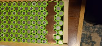
The scooter deck (home for battery) is a cast aluminum block and has zero flex and limited vibrations since it will be tucked in very tightly. Usable deck width is 172mm wide and 455mm long. The current wooden jig have the wrapped cells at 167.5mm wide and currently they're at 445mm long. My problem and question comes here... Due to the "W" shape layout of the cells, as I narrow the pack or add fish paper between the series groups, the length increases exponentially and I'm already cutting it close.
Would it be safe in my situation (no deck flex and limited vibrations) to wrap each cell with 1 or 2 layers of kapton tape instead of using fish paper to insulate the series groups? I plan on lightly sanding the cell wrappings so the hot glue sticks well. I have extremely good hot glue, the kind meant for auto dent removal and on my test cells it holds them together very nicely and secure. I'm confident with this method. Cells spacers are not an option in my case. Final pack will be completely wrapped in kapton and fish and heat shrink as a final wrap. Also using .3 thick epoxy resin board on the sidewalls. Is wrapping each cell in 1 or 2 layers of kapton sufficient? As I add the .25mm thick fish paper between each of the 20 groups, my length is now thrown off (.25mm fish paper x 20 pieces equals roughly 5-6mm of additional length), so trying to avoid using the fish paper if possible.
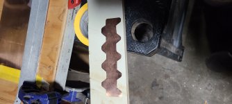
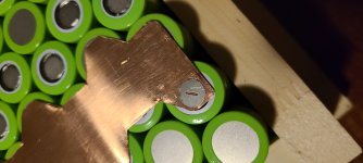
I bought the Malectrics V4 spot welder along with a strong Lipo (battery terminals purchased as a backup as well) and multiple types of material to do test welds before I settle on a particular material. I currently have 50mm wide .1 and .15 copper sheet (as shown in the picture), 50mm wide .2 nickel sheet, .15 nickel plated copper but only 10mm wide (not wide enough for 45mm wide "plates" so would need to use strips), .1 nickel plated steel and .15 nickel tabs with precut slots (see picture). The nickel plated steel and slotted nickel tabs are to use as welding tabs only and would go on top of the copper sheet to aid with the welds/heat, since copper isn't easily weldable on it's own.
Does anyone have a recommendation for which material to use as the parallel/series "plates" keeping the 15a(ish) cell discharge max in mind? Would the .2 nickel suffice in my case? Or should I try the copper? The plates and cross section is quite large, so not sure which way to go. 48 hour salt water test shows the .2 nickel sheets are as pure as it gets. Hoot hoot LoL.
The copper plate pictured was my first test template. I do plan on trimming the plates down to more accurate size to reduce the amount of possible shorts. I will also be adding another barley paper o ring to each positive battery end to protect from shoulder shorts.
I'm still brainstorming about how to make my terminal power wire connections to main negative and main positive. BMS will be sitting on top of the battery (made a custom 24mm deck spacer to raise the deck height to allow for this) and is 150a discharge continuous with 1a active cell balancing. Charging through Nucular controller with Eltek Flatpack2. BMS has common wires for discharge and charge, so no separate C- charge wire. Should work perfectly with the Nucular charge function. Discharge/Charge/Active Balancing modes are toggled within the app. BMS P- and B- are both dual 7awg wire, so planning on spacing those out on the terminal bus ends. Anti spark 150a connectors to be used.
I'm on hold until I can figure out the best way to insulate the series groups without affecting my overall length too much. I won't be gluing the P groups together until I settle on a comfortable solution. I'm not in a rush as it's winter time here and I still have my stock 16s battery as a backup for the time being.
As I progress, I'm certain I will have more questions and looking for suggestions on certain aspects. I figured this would be a good place to start since I'm unsure regarding my questions/concerns as stated above.
Any suggestions, concerns, criticism, comments, etc.. are absolutely welcome.
Very Much Appreciated Guys!
Adam
I'm somewhat new to EV and building my first custom battery for my electric scooter, Vsett 10+. I am looking for any suggestions and advice regarding a few things. I would really super appreciate any input and I am more than open to suggestions/criticisms.
I'll start by saying I have read through many of the discussions on ES regarding techniques, materials, power flow, etc... I've done tons of research and educating myself, so I do this right and safe. This is my first build and want to do it right the first time. I tend to be an overkill type of guy, so if any of my methods/materials seem outlandish, it's because I want to be safe in all aspects.
New battery will be a 20s9p 21700 Samsung 48X cells that arrived to me naked (unwrapped) and each cell was perfectly balanced at 3.58v. All cell imprints reflect that they are from the same run lot or batch. These cells have a continuous rating of 10a but tests (by Mooch on ECF) confirm the temps are safe and stable up to around 16-17a in moderate bursts. 48X cells have an estimated 3000 cycle life according to Samsung, so this battery may end up being used in a different frame in the future. So I want to build it with no bottlenecks or limits due to insufficient connections or wires.
The 1400w dual motors are rated at 60v (16s) and have injected each with 6ml of statorade from Grin Tech. I estimate at 72v I should be not be pulling more than 120-130 battery amps (13-14a per cell), even at peak. Dual Nucular 12F controllers can handle this with ease.
The scooter deck (home for battery) is a cast aluminum block and has zero flex and limited vibrations since it will be tucked in very tightly. Usable deck width is 172mm wide and 455mm long. The current wooden jig have the wrapped cells at 167.5mm wide and currently they're at 445mm long. My problem and question comes here... Due to the "W" shape layout of the cells, as I narrow the pack or add fish paper between the series groups, the length increases exponentially and I'm already cutting it close.
Would it be safe in my situation (no deck flex and limited vibrations) to wrap each cell with 1 or 2 layers of kapton tape instead of using fish paper to insulate the series groups? I plan on lightly sanding the cell wrappings so the hot glue sticks well. I have extremely good hot glue, the kind meant for auto dent removal and on my test cells it holds them together very nicely and secure. I'm confident with this method. Cells spacers are not an option in my case. Final pack will be completely wrapped in kapton and fish and heat shrink as a final wrap. Also using .3 thick epoxy resin board on the sidewalls. Is wrapping each cell in 1 or 2 layers of kapton sufficient? As I add the .25mm thick fish paper between each of the 20 groups, my length is now thrown off (.25mm fish paper x 20 pieces equals roughly 5-6mm of additional length), so trying to avoid using the fish paper if possible.
I bought the Malectrics V4 spot welder along with a strong Lipo (battery terminals purchased as a backup as well) and multiple types of material to do test welds before I settle on a particular material. I currently have 50mm wide .1 and .15 copper sheet (as shown in the picture), 50mm wide .2 nickel sheet, .15 nickel plated copper but only 10mm wide (not wide enough for 45mm wide "plates" so would need to use strips), .1 nickel plated steel and .15 nickel tabs with precut slots (see picture). The nickel plated steel and slotted nickel tabs are to use as welding tabs only and would go on top of the copper sheet to aid with the welds/heat, since copper isn't easily weldable on it's own.
Does anyone have a recommendation for which material to use as the parallel/series "plates" keeping the 15a(ish) cell discharge max in mind? Would the .2 nickel suffice in my case? Or should I try the copper? The plates and cross section is quite large, so not sure which way to go. 48 hour salt water test shows the .2 nickel sheets are as pure as it gets. Hoot hoot LoL.
The copper plate pictured was my first test template. I do plan on trimming the plates down to more accurate size to reduce the amount of possible shorts. I will also be adding another barley paper o ring to each positive battery end to protect from shoulder shorts.
I'm still brainstorming about how to make my terminal power wire connections to main negative and main positive. BMS will be sitting on top of the battery (made a custom 24mm deck spacer to raise the deck height to allow for this) and is 150a discharge continuous with 1a active cell balancing. Charging through Nucular controller with Eltek Flatpack2. BMS has common wires for discharge and charge, so no separate C- charge wire. Should work perfectly with the Nucular charge function. Discharge/Charge/Active Balancing modes are toggled within the app. BMS P- and B- are both dual 7awg wire, so planning on spacing those out on the terminal bus ends. Anti spark 150a connectors to be used.
I'm on hold until I can figure out the best way to insulate the series groups without affecting my overall length too much. I won't be gluing the P groups together until I settle on a comfortable solution. I'm not in a rush as it's winter time here and I still have my stock 16s battery as a backup for the time being.
As I progress, I'm certain I will have more questions and looking for suggestions on certain aspects. I figured this would be a good place to start since I'm unsure regarding my questions/concerns as stated above.
Any suggestions, concerns, criticism, comments, etc.. are absolutely welcome.
Very Much Appreciated Guys!
Adam