Ring gear / drone motor Ebike prototype

pf26

100 mW
Joined
Nov 17, 2014
Messages
49
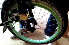
For those interested in low weight motors for Ebikes, I've used a drone motor (P60) and a (mostl likely) innovative gear reduction using :
- a large ring gear (module2) attached to the rim
- an intermediate external/internal freewheeling gear
- a spur gear gear module 1 connected to the motor axis
The intermediate gear is used to convert gear modules and allow for a larger gear ratio..
The motor/gear can be engaged or not using a simple cable arrangement - so this motor can feature regen too.
Gears were cnc cut in FR4 material (expoxy/glassfiber) using small end mills (1mm/1.5mm diameter).
Functional but noisy at speeds !

https://mv.omegawatt.fr/velo/ebike_ring1.mp4 or on vimeo
https://mv.omegawatt.fr/velo/ebike_ring2.mp4 (similar but with engagement cable view)
 
Excellent, I have wondered for so long why I couldn’t find anyone who explored this way of transmitting power to the wheel. It feels that it allow for lower torque motor, like friction drive, but with a more efficient coupling and indeed regen capability.
I’ve been toying with the same concepts (rim gear, intermediate gear to change the modulus, and some clutch/disengagement mechanism) but I have been held off by the strategy to build and attach the rim gear. I have carbon rims so I’m not too keen in drilling holes into them to make the rim gear hold.
Can you share details on how you managed that part of the build?

Cheers,
Stephane
 
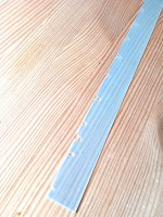
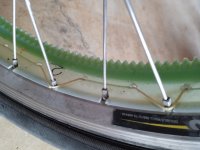
Thks ! The main ring gear was cut in 2 parts of 5mm thick FR4 using 1.5mm diam end mill and then glued one on top of the other to make it 10mm thick. Then I milled 0.5mm thin FR4 sheets (3 parts per ring) with slots to accomodate the spokes positions and glued two layers around the 10mm ring. Not so easy, but not so bad either..
The ring is kept in place on the wheel because spokes slots are tight and also using kevlar wire to prevent the ring to escape the weel..

IMG_20240228_112758.jpg

IMG_20240228_112655.jpg

IMG_20240228_112613.jpg
 
Very interesting!

What motor are you using, and at what power level?
 
I use T-Motor P60 170kV. It should provide more than 1kW at higher speeds, but currently very limitted by teeth escaping the ring gear contact - I need to improve this. Probably a higher gear module for the large ring would have helped.
 
Very nice idea. But what's the purpose of the small ring gear, it appears to do nothing to the gear ratio. If it's for freewheeling, how does this work?
 
The purpose of the intermediate ring is convert high gear module to a lower one, which makes it possible to use a smaller diameter gear on the motor, and in turn to achieve a higher gear ratio (near 20 on a "single" stage). The smallest module 2 gears have 12 teeth only and a somewhat larger diameter than the module 1 gear I used on this motor.. Also a relatively large intermediate gear makes more area of contact between teeth, meaning less mechanical constraints (and hopefully noise).
 
Forgot to mention that you need to be quite accurate in the rim internal diameter measurement, so that the FR4 ring will fit nicely. Also milling the spoke slots needs calculation, even when the 2 FR4 layers are thin, making 1mm diameter difference, leading to 3.1mm more on the circunference.. not negligeable : the 2 layers slots positions are different - I used XL to produce my GCode for the cnc machine.
Now about the resulting torque, be aware that this motor has only 1.5Nm max torque (possibly 2Nm for a short time), if well ventilated. I am low in weight and I like to drive fast, if not your case, you might need a higher gearing, or lower Kv motor than I.
 
I’m considering this kind of drive as a variation of friction drive in the sense that the power is transmitted close to the outer diameter of the wheel so there is no high torque/reduction requirement.
It may be slightly less true in your case since you look like using small diameter wheel and you had to attach it on the inner side of the rim because you have rim brakes.

Your internal gear is 10mm thick. Considering high torque is not a constraint, why did you make it so wide? Is it to compensate for wheel truing or simply structural strength?

Lastly, I’m concerned about dirt and mud getting into the gears and grinding them overtime. Do you have some observations about this?

Thank you
 
I have thoughts of doing something remotely similar with a very large toothed wheel attached in a somewhat similar way to the rim where the toothed wheel would be only slightly smaller than the rim. The difference would be that I would use a belt around the very large toothed wheel and then couple that with the corresponding toothed wheel on a motor with a tensioner. Since the actual tension on the belt would be relatively small compared to other mid-drive type drives, for example, I believe the belt could be fairly slender. One of the problems of this design is the excruciating noise that would remind me of a dentist office as I was using it. ;) . Anyhow, I think it's really worth exploring ideas like this where we get substantial gear ratio reduction without going through multiple stages.

something like this
 
Last edited:
10mm thick ring was choosen to reduce load on the teeth. The idea was to push approx. 100N of tire force to compensate for most of the bike+me+trailer load weight in a 10% slope. That's about 120N on the ring teeth, and assuming that it is spread on 5-10mm² of tooth area, make up to 24MPa of max constraint, which could be handle quite easily. As for dirt, yes I am concerned, I have yet to drive the bike on road enough to see how it behaves for real. Might be variable depending on the region where one lives.. And finally for the belt, I have a prototype using an AT5 timing belt and large ring quite successfully (requires high tension), but without possibility to disengage the motor while driving..
 
What did you mean by 'requires high tension' ? Does that mean that you needed a lot of belt tension so that it doesn't slip on the small pulley side? Can you comment on the noise of the belt versus the gear version? If I'm not mistaken, the AT-5 belt has 5mm pitch. Isn't that too fine for this purpose?
 
Just curious, have you considered shaft drive? I have seen em on bikes many years gone by, no idea if they are any good, just thought to ask.
 
Yes, the AT5 belt would required high initial tension so that it does not slip on the small pulley (the large pulley ratio makes the teeth only engage in a quarter of the small pulley - unless I added a belt tensionner - which I did, but at the expense of higher power losses it seems. Belt was completely silent compared to large ring gear. AT5 was a comprise to carry enough load (like 100N initial tension + 100N under highest load), not sure if smaller pitch like GT2 would stand this. -
@DaLanMan: As for shaft drive, I don't know what you mean precisely.
Finally, I read quite a lot on yasa motors, and am more interested in developping a thin, large diameter axial motor, hollow in its center (using large thin section bearing), attached to the disk brake caliper fittings on the bike frame, and rotor connected to a few spokes..
 
Yes, the AT5 belt would required high initial tension so that it does not slip on the small pulley (the large pulley ratio makes the teeth only engage in a quarter of the small pulley - unless I added a belt tensionner - which I did, but at the expense of higher power losses it seems.

You have rediscovered two of the problems with belts. Minimum tension that's too high for best function of the other parts, and relatively poor efficiency.

If you locate the idler pulley so that it maximizes belt wrap on the motor sprocket, then the minimum operating tension can be lower. In your case, the close spacing of the sprockets prevents the idler from getting as much wrap on the motor sprocket as would otherwise be possible. Ideally, you'd have a majority of the small sprocket's teeth engaged at any time.
 
Yes, that were reasons for me to try the large ring gear instead belts. Along with the easy disengagement of the motor. But still noise problem and probably long term wear due to dirt might make it stay an idea more than my everyday motor. Possibly some will reuse and improve the "ring in a ring" principle to convert different gear modules and increase gear ratio - this may open up new designs possibilities, who knows.
 
I'm not understanding the loss of efficiency of having an idler roller on the belt. Would that simply be a matter of the bearing spinning drag? For me, it doesn't matter how close the motor is to the wheel. So I can envision having a belt wrap around slightly more than half the motor pulley and with a good quality ball bearing providing the idler function, wouldn't the lock be only a few percent?
 
The idler roller on the belt increases its curvatures and consequently its losses as far as I understand it.
 
The idler roller on the belt increases its curvatures and consequently its losses as far as I understand it.
So to mitigate this as much as possible, the goal would be to use an idler bearing with the largest diameter feasible. I think I have this correct. Secondarily, it's best to use the largest pulley on the motor as well. The overall limiter on this is to get the largest possible pulley onto the rear wheel. In other words, have the pulley be almost the same size as the rim.
 
@marka-ee : yes - also be considering that very long belts are not available for so specific length you might need...
I also tried to use idler roller directly against the little pulley to prevent belt teeth to escape the pulley, but this might put some more wear on the belt for some reasons, I never saw this as a "standard" way to proceed with timing belts..
 
@DaLanMan: As for shaft drive, I don't know what you mean precisely.
Finally, I read quite a lot on yasa motors, and am more interested in developing a thin, large diameter axial motor, hollow in its center (using large thin section bearing), attached to the disk brake caliper fittings on the bike frame, and rotor connected to a few spokes..

I might be aging myself, and this is not a yank the chain kind of thing, it is just that when I used to sit in an area with a bunch of enthusiastic cyclist one of the hot topics of discussion was the viability of a .. to be released? recently release? not sure direct shaft drive, so instead of an external rotating belt/chain you had a sealed run shaft (like the drive shaft on rear wheel drive cars etc) that opened at a universal joint type object that connected to the drive motor.. not sure how that was happening, I really did not follow the conversation that well for the most part, was just kind of there when it happened.

With that said, I think it would be cool to have a drive shaft on a bike... I have even seen rear end units for trikes that include the option for a splined input as opposed to an external sprocket.

I am not making things up I swear (I asked a buddy today about shaft drives and if had heard of them, his response "look man I know you get a kick out of yanking chains, but stop. Bikes use belts or chains"
Google is my friend
 
Back
Top