sabvoton 150 controller issues

syrus420

10 µW
Joined
May 22, 2024
Messages
5
Location
usa
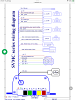
HI everyone! I messed up my sabvoton controller, I'm not to sure what I did wrong. The last time I rode it I was going pretty fast and the bike shut off on me, when I got it home I noticed the battery had a ANL fuse that was broken, so I soldered a new one and noticed next my sabvoton was not turning on so I took it apart. I found a lose brown wire that I cant find where it goes and was hoping someone may know and also I noticed a area on the motherboard where looks to be a surface mount component to be missing.
 

Attachments

  • image_123923953(3).JPG
    image_123923953(3).JPG
    2 MB · Views: 13
  • image_123923953(4).JPG
    image_123923953(4).JPG
    1.6 MB · Views: 13
How many amps were you pulling, on what voltage, on what model of controller?
 
Did you tune it at all?

Hoping someone can help you find where the loose brown wire goes!
 
I did the hull senor test on my phone via app then saved the configuration and rode the bike for 3 or 4 times in the span of a week. Before the last time I rode it I went into the app and setup the E-braking/regen via a video I followed on youtube using there settings. I don't know if it matters but I'm a tall and heavy rider 300lb
 
Does the brown wire go into a 3 way plug together with a black and red wire?

If it does then I think it is for 0-5v ebrake throttle signal. I can’t help where it is supposed to be soldered onto the pcb though, but It shouldn’t stop the controller and display from turning on.

Have you checked that you still have 72 volts from the battery after replacing your fuse?

I have found that it is quite easy to overheat the QS205 if I give mine a lot of abuse with lots of hard accelerations coupled with hard ebraking and I’m only using a 72100. My ebraking is set at 30 amps, operated via the brake switches which I think is fairly mild. I don’t have an ebrake throttle.

I kept on blowing hall sensors when the motor got hot, so I have replaced all 6 hall sensors in the motor with new SS41 rated at 150C.

And I replaced the KTY 83 temperature sensor in the motor with an NTC 10K temperature sensor and have a separate temperature meter with an alarm set at 90C.

I also fitted an NTC 10K inside the controller next to the existing temperature sensor to independently monitor the controller temperature and set that alarm for 70C.

Now that I’m keeping my temperatures down it is operating reliably.

All of this was done on a brand new motor and controller while ironing the bugs out on a new build.

It may also be worthwile for you to check the brake disc screws haven’t rubbed on the motor cable. Mine did this on the test stand and severed the insulation on a couple of phase wires, so I had to order a spacer from Ali Expess to solve that problem. I was lucky the wire’s didn’t short together and blow the Mosfets. The orange coating on the motor cable seems to be as soft as butter.

I had to cut the motor cable to remove the damaged section and rewire it to the motor. The spacer is available on eBay for around 12 dollars if you are based in the US.


That’s all part of the joy when doing a diy build. Someone on this forum did write that the QS205 is “a difficult motor to work with“ and they were not kidding. But it’s great when you can get it to run right. It has so much torque and speed.


IMG_0190.jpeg

.


IMG_0189.png
 
Last edited:
Sorry for the late response work/family, I looked over the the wiring on the bike from the motor to the controller and there not frayed or broken. I checked the battery voltage from the main port and charging port and they read the same voltage. For the wires I noticed the controller has 3 brown wires, 2 thinner wires and 1 slightly thicker wire. The only brown wire I see from outside of the controller is the one I need to unplug so I can use the app for tuning.
image_123923953(5).JPG
 
Last edited:
This is the best photo I could find.

On this controller it looks like brown, yellow and green are soldered to the board labelled 1, 4 and 6 on top left. With brown to 1, yellow to 4 and green to 6.

The wires on the return connector, black, yellow and green look like they are soldered to the board just to the left of them.

It would make sense for all of these wires to be clustered together in the same place on the pcb. But there is of course no guarantee that yours is wired the same.

Although on this controller there is another brown wire on the left hand side and I can’t see where that goes. It’s possibly an ebrake throttle signal wire.

None of the photos in the linked thread show resistor R184 clearly, so I have no idea whether it has blown or not.

The photo comes from this thread:


IMG_0192.jpeg
 
Last edited:
Back
Top