• Howdy! we're looking for donations to finish custom knowledgebase software for this forum. Please see our Funding drive thread

singnalab BMS "Damn it Jim, He's Dead!"

h82w8v6

10 mW
Joined
Feb 7, 2014
Messages
33
well I started this thing with no bms on a NEW DIY Headway pack 10ah. Nothing special.. The original BMS "Red resister board" blew as soon as it was hooked to the pack, so what to do..... adjust the charger down to 55v and try to keep it on the safe side.....
Next was on to a China special from e Bay 60A peak.... had no luck with that one.... Now im cursing every word in the book, and onto two months with no BMS ( i have been monitoring the cells)
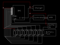
3ed BMS and now onto a Signalab (LEDs) the pic that I have attached is the diagram that i followed and have seemed to installed with success or so i thought..... turns out the charger wont turn on (WTF) reset and still nothing..... so now i try to charge by bypassing BMS, and presto it starts charging! Now check all connections once again..... ALL wires are firmly in place, probes connected and soldered, and from the pin out everything goes in order from black to gray, to red (3.3-6.6-9.9) all the way up to about 55.2v..... all looks good to me.
Now I did notice that once I bypassed the BMS and continued to charge to full, and the very quickly attached my bms all the LEDs were lit up, and one by one started to fade out.... this was with only the probe wires (1-16) and B- to NEGATIVE of battery.


At this point I am wondering what my option may be, looking for a bit of advice from someone who has more experience then myself with BMSs.... I have wasted about $150.00 on these darn things.....
To my knowledge there is no damage to the current Signalab bms..... :evil: :evil:

is there a adjustment I can make to my charger
is there an adjustment to the BMS that i could make ( take out heat probe/ replace with switch or just solder contact open?)
is there a way to just use the balance function of BMS and trick the sys so i can still balance charge


any help would be greatly appreciated
 

Attachments

  • bmsbattery.png
    bmsbattery.png
    2.8 KB · Views: 1,910
Hey h82w8v6!

Welcome to ES 1.jpg

OK, I am not sure I understand your wiring diagram....Are you really running a 14s Headway battery pack? And I am not sure about your charging methods.....Headways charge to 3.65 per cell or 14 x 3.65 = 51.1 volts. All of this seems non-standard to me...

As far as I am concerned a cheap BMS isn't worth the trouble or the cost of replacement. I have come to the conclusion that a quality BMS is worth the extra dollars because the batteries are expensive and I want to protect mine.

How about this:
Please post the model numbers of the BMS's you burned out and if you can as many pictures of your battery build and burnt bms's as necessary to give us a good look at what you have.

You don't seem to be going standard, so if you want to go custom, we need more info...

Anyway, welcome to ES

:D
 
your BMS may have been blocking the charge because it detected one of the cells was above the 3.9V HVC.

do you have a connector in the B- cable from the BMS to the battery? is that watts up soldered inline?
 
ok sorry I was not a clear as i should have been, the battery is a 16s, and i only used the diagram as reference. The charger is a 4 amp and I did turn the charger back up to 61.2v. HVC is 3.8v per cell i think.... and i witnessed two of the cells attempting to go past 3.8 , when i seen 3.9v i shut down the whole sys.I presume the cells will go higher if allowed and i dont want to kill these things. As of now i only am using the bms as a LED display...... B- to battery Neg is and still is connected.
 
3.9V will not kill the lifepo4. you should set the charger voltage to 16X3.60V if the balancing voltage is 3.60V. plus i always add a little extra to force it to balance faster. 57.6+.8=58.4V should be effective in balancing the pack. that gets it to full charge, but it is best to keep it to 3.60V after that since the lithium plates out above 3.60V so once it is balanced you can leave it close to 57.6-57.8V imo.
 
also I reside in the Orlando, FL US area.

For some reason I am thinking that the charger is not seeing a LOAD and this is why it is not activating......

Here are some pics of what i have
 

Attachments

  • 1010991_10201383321207487_45787815_n.jpg
    1010991_10201383321207487_45787815_n.jpg
    81.2 KB · Views: 916
  • 1504049_10201279220325030_1567080444_n.jpg
    1504049_10201279220325030_1567080444_n.jpg
    93.3 KB · Views: 916
  • IMG_6690-1.JPG
    IMG_6690-1.JPG
    47.7 KB · Views: 1,860
dnmun said:
3.9V will not kill the lifepo4. you should set the charger voltage to 16X3.60V if the balancing voltage is 3.60V. plus i always add a little extra to force it to balance faster. 57.6+.8=58.4V should be effective in balancing the pack. that gets it to full charge, but it is best to keep it to 3.60V after that since the lithium plates out above 3.60V so once it is balanced you can leave it close to 57.6-57.8V imo.


thanks for the advice, I have turned the charger to that exact reading.... but keep in mind this is bypassing the bms..... I have yet to charge through the Signalab and balance properly. At this point in time there is no evidence showing any damage to BMS. wish i knew what to do.
 
dnmun said:
why are you charging with no BMS? if you have it there why don't you use it? how will the pack balance if you don't?


when i run through the Sinalab the charger will not activate. When i bypass bms, I then can charge. Thats the whole problem.
 
And this is the genaric charger setup......4A now set to 58.4v constant charger.
 

Attachments

  • IMAG1015.jpg
    IMAG1015.jpg
    165.1 KB · Views: 815
h82w8v6 said:
And this is the genaric charger setup......4A now set to 58.4v constant charger.

Take a voltage reading from your battery positive to the negative charge lead from the BMS. Make sure you are reading a voltage, and the same voltage as you obtain taking a reading from the negative power lead from the BMS.

Although I'm sure the 4a is under its rating, but out of curiosity, what charging AMP is your BMS rated for?

Wishes
 
BMS/PCB for 48V(16S) LiFePO4 Battery Pack(50A +/-10A limit)With Balance Function
 
About BMS/PCB/PCM for 48V(51.2V) LiFePO4 Battery Pack (16 cells with 50A +/-10A limit ) With Balance Function:

Describe

Model: BMS16LF
BMS(Battery Management System)For 51.2V LiFePO4 Battery Pack, Different with normal PCB, it provides equilibrium function after battery pack is fully charged, e.g. PCM(Protection Circuit Module) will detect each cell's voltage and trim higher voltage until other cell's voltage reach same,therefore allow LiFePO4 cell has longer service life. Also the PCM will provide the following protections:
* Balance each cell at Max. 3.80/cell ( required voltage tolerance within 0.2V for each cell);LED indicator for full charged cell indication, balance is finished when four LED lights were on
* Overcharge protection voltage for single cell: 3.90V +/-0.025V
* Overdischarge protection voltage for single cell: 2.10V +/-0.05V
* Continus working current: 30A
* Overcurrent detection protection: 50A ~ 60A
* Charge voltage: 58V
* Charge current: 5A
* Supply current: Max 30uA
* Short circuit protection
* Protection circuitry resistance: <=50mohms
Applications
Apply for 16 Cells LiFePO4 Battery Pack with discharging current < 30A.
Internally Trimmed Voltage Limits to balance each cell. Please wait 30 minutes for this equilibrium function to take place after charger indicated battery pack is fully charged.
30A Discharge Current Limit Detection.
come with wires and connector
Size: 4.7" x 2.4" x 0.4"

Net Weight: 2.30 oz
 
* Charge current: 5A, this may be what my problem is here! My charger is not putting out enough Amps, Right? Hmm.... what do you think.....
 
if you cannot charge through the BMS because the charging mosfet is turned off then it is likely that you have either miswired the BMS or the cell voltage is above 3.8V still.

usually the mosfet is shorted when it fails so if you cannot charge with the BMS present then it most likely is still functional.
 
Do a small discharge of the pack. Check cell voltage. Then charge again thru bms if wiring is correct.
I like an extra set of sense wires two 8s and a cellog 8 for ez checking and to help a low or high cell ect.
 
It should charge with anything less than 5amps. So the 4amps charger is definitely not why. dunmum is right, if it isn't charging it is because the mosfet is off. If you have taken a voltage reading of all your individual cells and you know for a fact none of them are above 3.8v, then it has to be your wiring. The wiring diagram you posted was just an example and not your actual wiring. Do you have that wattsup meter in your setup?
 
Wishes said:
h82w8v6 said:
And this is the genaric charger setup......4A now set to 58.4v constant charger.

Take a voltage reading from your battery positive to the negative charge lead from the BMS. Make sure you are reading a voltage, and the same voltage as you obtain taking a reading from the negative power lead from the BMS.

Although I'm sure the 4a is under its rating, but out of curiosity, what charging AMP is your BMS rated for?

Wishes


test results are as followed....

reading from C- / BATT + = 58.5v this is my charger assigned output
reading from B-/ BATT + = 54.2v this is my battery current charge state

did i misunderstand you? what should i be looking for to test if bms is passing a charge.

1/ 3.6
2/ 7.2
3/ 10.7
4/ 14.1
5/ 17.5
6/ 20.9
7/ 24.3
8/ 27.7
9/ 31.1
10/ 34.4
11/ 37.8
12/ 41.3
13/ 44.9
14/ 48.3
15/ 51.7
16/ 55.3

also what is the random flashing from the bms signify?
 
measure the gate voltage on the charging mosfet.

use the 20V DC scale.

put the black probe on the B- spot, and put the red probe on the left leg of the charging mosfet. next to C-.
 
1/ 3.6 = 3.6
2/ 7.2 = 3.6
3/ 10.7 = 3.5
4/ 14.1 = 3.4
5/ 17.5 = 3.4
6/ 20.9 = 3.4
7/ 24.3 = 3.4
8/ 27.7 = 3.4
9/ 31.1 = 3.4
10/ 34.4 = 3.4
11/ 37.8 = 3.4
12/ 41.3 = 3.5
13/ 44.9 = 3.6
14/ 48.3 = 3.4
15/ 51.7 = 3.4
16/ 55.3 = 3.6

That is your individual cell levels. They are within the tolerance of the BMS board. LIfepo4 don't usually hold their 3.6v fully charged for very long, it tends to drop to 3.4ish after you remove the charger. I'm surprised to see so many cells holding their 3.6. But i've never worked with headway cells specifically.
 
Wishes said:
It should charge with anything less than 5amps. So the 4amps charger is definitely not why. dunmum is right, if it isn't charging it is because the mosfet is off. If you have taken a voltage reading of all your individual cells and you know for a fact none of them are above 3.8v, then it has to be your wiring. The wiring diagram you posted was just an example and not your actual wiring. Do you have that wattsup meter in your setup?

I am not using the watt up meter, and yes that was just an example.... it was the one example that i could find with clear precise wire diagram.
When you speak of the MOSFET being OFF i am afraid i am not sure what you are talking about..... describe please.
 
Wishes said:
1/ 3.6 = 3.6
2/ 7.2 = 3.6
3/ 10.7 = 3.5
4/ 14.1 = 3.4
5/ 17.5 = 3.4
6/ 20.9 = 3.4
7/ 24.3 = 3.4
8/ 27.7 = 3.4
9/ 31.1 = 3.4
10/ 34.4 = 3.4
11/ 37.8 = 3.4
12/ 41.3 = 3.5
13/ 44.9 = 3.6
14/ 48.3 = 3.4
15/ 51.7 = 3.4
16/ 55.3 = 3.6

That is your individual cell levels. They are within the tolerance of the BMS board. LIfepo4 don't usually hold their 3.6v fully charged for very long, it tends to drop to 3.4ish after you remove the charger. I'm surprised to see so many cells holding their 3.6. But i've never worked with headway cells specifically.

this was hot off the charger, without BMS and i pulled it off as some cells were reaching 3.9-4.0v
 
dnmun said:
measure the gate voltage on the charging mosfet.

use the 20V DC scale.

put the black probe on the B- spot, and put the red probe on the left leg of the charging mosfet. next to C-.


is this what you are talking about?

with charger attached the reading is -0.45v
with out charger connected 45v
 

Attachments

  • IMAG1019.jpg
    IMAG1019.jpg
    151.7 KB · Views: 1,820
Back
Top