size of resistor to discharge Moli 18650 1.4 ah cell

katou

10 kW
Joined
Jul 22, 2009
Messages
791
Location
Toronto
Hey, I want to make a little circuit to discharge a single moli cell to check capacity, and I'm wondering what size of resistor to use.

I figured that I'd try to get the discharge time to be similar to "in use" discharge times.

I am guesstimating that a whole pack would probably get me 1-2 hrs of run time.

So, what size of resistor would be appropriate to drain a cell like this over 2 hrs or so?

I am aware that I can calculate the value, but this does not take into account the dropping voltage, and that's what confuses me.

Thanks!

Katou
 
Correct. As the voltage drops on the cell, so does the current.

What you need is a constant current load - EMoli is a similar terminal voltage to Lipo I think? 4.2V charged, 3.7 nominal, 3V 100% DOD?

Have a look at using an LM317 or LM350K set up as a constant current source - the device will be shedding the load as heat (like a resistor) so use a steel-case TO-3 rather than TO-220 depending on your current requirements. This is less suited to a lower voltage cell like LiFe due to the 2.5V reference thats needed.

TBH a resistor is a crappy load for a cell - halogen bulbs are better - their cold resistance (at lower voltages) is lower than their hot, so they are a more suitable load. Place a fully charged cell on the load, and run it down to LVC, and stop. Measure the time. Gives you a relative measurement of capacity.
 
Must consider this, and research the parts you mentioned...

Thanks for the info, just what I needed. I had hoped to get away from constant current issues, but now I understand it is unavoidable.

Katou
 
Although resistors are not ideal you can still use them to get a good approximation of the capacity. If you decided on approximately 1 hour discharge you could use a 3ohm resistor and this would give you roughly 1.2A initially and then reduce as the cell discharged. You would only be pulling about 5W so if you used something with plenty of capacity in reserve like a 20W resistor it shouldn't get hot and should stay fairly constant resistance. As long as you monitor the voltage during the discharge you can calculate the current, or simply measure it directly as we're only talking about just over 1A. Even if you just jot the numbers down and plug them into excel you can get a good idea of the cells Ah capacity.

I made a test rig using a cell log 8S with the alarm signal used to disconnect the load when a cell hit the LVC. You could use the same idea to string together 8 cells and discharge them simultaneously. This will give you a good idea of the relative capacity of each cell in the string of 8 cells. It's not important to get the absolute capacity value as long as you can determine the relative values.

heathyoung said:
Have a look at using an LM317 or LM350K set up as a constant current source - the device will be shedding the load as heat (like a resistor) so use a steel-case TO-3 rather than TO-220 depending on your current requirements. This is less suited to a lower voltage cell like LiFe due to the 2.5V reference thats needed.

I'd be very interested in some more pointers in how to achieve a constant current load. Maybe you could elaborate a bit more :)
 
Cell Man, this is exactly what I want to do, discharge a string of them at the same time, noting which one drops first.

The load I put on each cell must drain a high capacity and a low capacity cell at the same rate. A resistor, since it is voltage dependent for the load, will not do this.

I need to drain the high cap and the low cap cell at the same rate. Even if one is at 3.7v and one is 2.9v. This is the reasoning for Heath's suggestion of a constant current load.

I had hoped to avoid the higher complexity and cost, but now I see it is unavoidable.

Katou
 
http://users.telenet.be/davshomepage/current-source.htm

http://en.wikipedia.org/wiki/Current_source#Active_current_sources
 
If you string say 8 cells in series and you monitor the voltage on each using a cell log 8 you will get an idea of the relative internal resistance of each when under load. All the cells in the string have to deliver the same current so the Ah delivered is equal at any time during the discharge. If 1 cell drops to the cut off voltage before another you can be sure it has lower capacity. A cell that has more voltage sag but delivers the same Ah will deliver less Whrs due to the lower voltage that cell is supplying during the discharge but it still delivers the same Ah. The fact that you have several series cells means that the current is likely to be more consistent between tests. The cell log 8 will also give you the pack voltage. It is very simple to just do a calc in excel to determine the current in the circuit from the resistance used. If you do this for each sample you can calculate the Ah for the pack and from this you can see what each cell delivers and at what stage it has discharged.

I can assure you that if you use this method you will very quickly get a good idea of the relative performance of the cells you are testing and there is no reason why the load has to be constant current to obtain meaningful data. I agree constant current is nice but the next best option is constant resistance IMO.

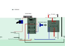
Here's some details of how to hook up a cell log to disconnect the load at a specified voltage

Dual Relay_v2.jpg

Here is a test bench I made using the methods I've detailed:

 
amberwolf said:
http://users.telenet.be/davshomepage/current-source.htm

http://en.wikipedia.org/wiki/Current_source#Active_current_sources

Correct. Use high power device packages like a TO-3 due to the heatsinking requirements. The output simply gets shorted and the device maintains a constant current across the load (rather than the LED in the first example - short to ground). Use 5W wirewound resistors as the resistor gets HOT too.
 
Back
Top