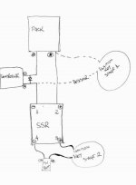
Solid State Relay circuit

Why don't you use an ignition switch?
2750025.jpg

http://www.ebay.co.uk/itm/130615005382?ssPageName=STRK:MEWNX:IT&_trksid=p3984.m1439.l2649#ht_966wt_1115

If you buy switch for boat/car battery, you should have high voltage/amp enough even for big current.
 
Sorry, I just gave you this one as example.

Here's a switch for boat I found quickly on ebay:
http://www.ebay.co.uk/itm/Heavy-Duty-Fixed-Key-Battery-Isolator-Switch-300A-/110729023022?pt=UK_CarsParts_Vehicles_CarParts_SM&hash=item19c7f6ce2e#ht_485wt_1644

It can handle 300A at 12V = 3600W continuous.

You can find other type of switch with other form factor if you search a bit more.
 
Yes, this will work for sure. But is HUGE, and my intention is to use a single ignition key to serve as a pre-charge and a heavy duty switch.

In other side, a ignition key is nice to have, too! :mrgreen:
 
You probably don't need an heavy duty switch if you have a pre-charge resistor.

What about having an heavy duty ignition key?
7.jpg

http://www.ebay.co.uk/itm/Key-Switch-Security-Lock-HeavyDuty-Keyed-Power-Ignition-/170655659064?pt=LH_DefaultDomain_0&hash=item27bbdeb438#ht_1243wt_1348

It's not that big, and you can even stack few of them if you don't realize it doesn't handle the amps.
 
sure it will work (as will the first switch posted)
-mount the SS relay on a big chunk of heatsink and prepare yourself for some V loss (not much, mind you, but with the current demands the SS will have significant heat generation on the order of 25 watts or so)
 
Thanks for your input, ddk...

Is because of this (v loss and heat generation) that we never see setups like this?

In your opinion, what would be best:

- a mechanical relay;
- a small battery pack used to activate the SS relay and at same time give power to a small cooler installed in the SSR;
- a DC-DC converver, activated by the same "first stage of the ignition key" supplying energy for the SSR activation and a cooler (and to a 12v outlet, of course :mrgreen: )

- Fabio
 
the SSR should use less current than an equivalent mechanical relay.
As for powering options I'm in agreement of using dc-dc converters in theory. In practice I use external small-ish, rechargeable batteries.
Also in practice I prefer switches.
You want a keyswitch to do lots of stuff. I'd simply use the keyswitch to turn the controller off/on.
 
yep
switch contacts and for that matter, connector contacts are rated for current-carrying capacity and current break-without-welding, not necessarily "watts".
Low voltage systems successfully can utilize switches with "12v" ratings because the voltage rating means something else other than the switch's voltage-handling (flash/flaming above 300 volts, generally)
All my switches are automotive-types on my battery packs and power-selector systems. Never had a contact failure.
 
Ypedal said:
http://www.ebay.com/itm/100-Amp-Disconnect-Knife-Switch-100A-Two-Pole-Circuit-Breaker-Backup-Generator-2-/170881623181?pt=LH_DefaultDomain_0&hash=item27c956a48d

Well now..... :?
want.jpg
 
fabiograssi said:
That is very very nice to know! :mrgreen:

Just one small for the precharge positive, and one big for the load positive cable! Simply as that?
yep
 
i still think it is easier to put a switch in the circuit current trace on the BMS. that shuts off the battery totally so it cannot short and the inrush current can be handled by the mosfets when you turn the circuit current back on. that avoids the precharge resistor.

you could even use a tiny micro switch or magnetic reed switch that only you could activate with a magnet in the right place.

i am gonna get some of the single dip switches on ebay to use in the spot where it goes on the BMS.
 
dnmun said:
i still think it is easier to put a switch in the circuit current trace on the BMS. that shuts off the battery totally so it cannot short and the inrush current can be handled by the mosfets when you turn the circuit current back on. that avoids the precharge resistor.

you could even use a tiny micro switch or magnetic reed switch that only you could activate with a magnet in the right place.

i am gonna get some of the single dip switches on ebay to use in the spot where it goes on the BMS.

Well, appears like an excellent idea, but I don't have the knowledgement...

Just to try to learn something, if this was the BMS, where is the place for that?

P6130101-001.JPG
 
it would be under all the black goop on the pcb. on the ping signalab there is a small rectangular set of brackets (next to the sense wire plug on v2.5 and next to the charging mosfet on v1) where the circuit current flows through a trace on the pcb. it is where a thermostatic switch would normally be wired in.

cut the trace that runs between the two holes, on the backside, and then run a two wire up from there to your switch or put a dip switch right into the holes and solder it in place.

take a picture of the underside in the middle, close enuff to read the traces and we may see where the thermal switch is wired in to that BMS.

edit: found a Vpower BMS: ok, if you look just above the black goop in the middle there may be two little spots where the B+ comes up from under the pcb. that is where the voltage for the LVC and HVC signals comes from so if you can find the traces that go out to the little transistors, on the collector end through a small resistor, then that is the circuit current on these Vpower pcbs. so it is possible on these Vpower BMSs too.

i can see on mine where the trace that carries B+ up for the LVC and HVC transistors coming off the B+ plane on the edge and goes under the black goop. that would be where to put the switch.
 
Your original circuit looks pretty good to me. Nice idea. Also push button for pre charge with led , and a key switch would be OK. Or led with pre charge and 2 stage key switch. Set voltage for led with resistor in series to work with pack voltage and all in parallel with a 100 ohm resistor 5 or 10 watts. High brightness led would look so cool!
 
pendragon8000 said:
Your original circuit looks pretty good to me. Nice idea. Also push button for pre charge with led , and a key switch would be OK. Or led with pre charge and 2 stage key switch. Set voltage for led with resistor in series to work with pack voltage and all in parallel with a 100 ohm resistor 5 or 10 watts. High brightness led would look so cool!

I am total dumbass in electronics. If you can draw your idea, will help me (and maybe others like me) a lot.

Just to clarify, my original intention was use just one "ignition key style drum", and wire the stage 1 (of my original drawing) in the first key position and stage 2 in the second key position, but a led will be really nice.

Can you draw for us?

- Fabio
 
Back
Top