"spokeless" bicycle....

Joined
Apr 17, 2008
Messages
607
Location
Ankara, Turkey
'

http://www.gizmag.com/spokeless-bicycle/14216/

Looks like this would be fun to electrify..... :wink:


spokeless-bicycle-4.jpg


spokeless-bicycle-1.jpg
 
Nice, no cheating by using a $5000 bearing either. Those sidewerds wheels retaining the wheel reminds me of rollercoasters.. Deffo would be very easy to add a motorization!
 
I've seen pictures of spokeless motorcycles but never a bicycle. Way cool. It looks like you could really use the space inside the wheel for panniers or a rack. +++ on the motor VI.
otheDoc
 
Was a thread not too long ago with a 'backyard' builder who made a bicycle chopper
with custom spokeless wheels he made. He used wheelchair push rails and rollerblade wheels, i was hoping the
person that posted the link could hook us up again, i seem to have not bookmarked it and
would perhaps like to replicate this one day...

Cheers in advance

KiM
 
is this the one KIM?
http://bikerodnkustom4.homestead.com/hubless_horseman.html
which would be wierd, cause you posted it. Must be some good shit growing in OZ :mrgreen: I have some skateboard wheels that are coming my way and I am planning on using some larger scooter wheels to build my own centerless wheel like the bushpigs but using an electric for that stealth ninja action. those two strokes are wicked annoying for both driver and observer.
 
lester12483 said:
Whats the point to spokeless wheel? What purpoe does it serve?

Cause it's different.

...well that's all I can think of, but if anyone else thinks else.
Battery storage space?? lol
 
Sorry guys - had to weigh in after Lester's question...

There are so many points it's not funny!!!

1.) Notice that the wheel is held in a tract way (assumed on bearings but magnetic rails or segments would be the lowest friction method (thing mag lev train) but i don't know how that may effect a motor but it's a valid point for research.

2.) Notice the small drive cog in relative terms... this is in effect a great reduction of and unto itself and would make the use of higher power, higher kV or even lower power but higher kV motors from the RC market without too much (if any) reduction

3.) Please note the drive gear/cog location? It's at the top most point (of the wheel), let me ask you, how much ground clearance does your normal bike have for the chain? Surely not 26" (approx 24-26 for a 26" bike). This location is also prime for a first stage belt reduction above it and above a fender (if needed even) - a design like this would have to be custom (or Aussie Jester) frame and all but... it would be a great platform for high kV/RPM inrunners and in all conditions (12" of snow is nothing when the drive component is 20" high and the wheels are covered (fairing hubcap, etc) to protect them. - Really they would be hub motors of a kind with the drive gear located atop the wheel instead of the center.

4.) Looking at my mountain bike, I can already see how such a wheel could be integrated with simple frame clamp on mount system or have the wheel come with a std 8sp internal gear and a through axle for quick release hub - that would solve the problem of equipping the higher end bikes (front or rear really) with simple bolt in kits. (this may have been done already but not to my knowledge).

5.) Personally I know I prefer MAG style wheels for 20" and if they could be done properly (billet 3x3 arm) for 26 in magnesium then the weight would be moderate to light and the strength for 26" bikes (lacking in mags now) would be there.

6.) Maintainability - ever try to service a hub motor internally?, this would be simple as removing a shield then the burnt motor (or controller) and replacing them - forget serviceability, think UPGRADING in a plug and play fashion with the RC motor industry.

Okay, sorry but i saw this and had to put it out there - will it catch on, probably not but in my humble opinion it should - it's an elegant design and could be aplied to solve many of our current technology issues with eBikes.

-Mike

PS:

I do see issues (possible) such as:
1.) How much torque can one of those drive systems handle - can we use off the shelf or is this back to fabrication 101 for even the drive tract? If we have to fabricate even down to that level, I think its too much for now.

2.) A fully sealed wheel (fairings like a motorcycle) even lexan would provide some protection from water, rain snow and debris) but is it even needed, what are teh effects of teh elements on the drive system if they experience rain or snow, slippage, etc?)

3.) Is it patented (with a valid and correct patent - meaning it's so obvious (actually is no more than a simple inner drive gear, not rocket science and ive seen plent of really close art - back to popular mechanics from the 60s)?

and one more plus:

Assuming a 20" wheel with a rim inner diameter of 18" if the drive is 1" diameter (I know it has to be larger for wrap (tensioners) then would that not be an 18:1 reduction so a motor / voltage combination running up to 6048 RPM under load would indeed provide full 20mph (18 gear inches in a single step!) - Here we only need chage the drive gear and tensioner to adjust the maximum speed the motor has been geared for... very simple really and considering a motor mount possible anywhere but the traction point of the tire (higher up is better for weather riding, lower for weight distribution).

Well... I am actually done now... sorry for the rant but this thread has been inspiring!
 
what about suspension?
direct contact with the road without isolation has gots to be hard on the drive train.
i would expect the washboard ride of a road-luge.
if roads were glass smooth & free of grains of sand & dirt the way it is in a cad rendered universe then it might work okay.
 
I would assume the simplest manor would be to attach to the normal frame dropouts via standard 8mm skewers (the torque is not on the dropouts with this drive system). That would enable whatever suspension the bike already had to take effect (front and or rear) which on a nice DH bike or even my low end folder (downtube 9FS) would make the ride very nice.... Nothing says we can't use pnumatic tires on the wheels? The drive cogs are on the inside of the rim ring (right?) which wouldn't interfere with a tire?

This is really just a big open internally geared hub motor without applying the torque to the weak link dropouts, making reinforcement un-needed. The contact tension between the drive unit and the inside of the wheel (the drive belt, teeth, gear, et) would be maintained regardless of suspension positioning.

Correct me please if I am wrong, am I under estimating the value of spoked wheels as an integral part of the wheel suspension or am I right in assuming those properties can be reflected in choice of material for the wheel?

Regards,
Mike
 
mwkeefer said:
Correct me please if I am wrong, am I under estimating the value of spoked wheels as an integral part of the wheel suspension or am I right in assuming those properties can be reflected in choice of material for the wheel?

Regards,
Mike

I think one issue would be getting/keeping the rim true myself. The tension of the spokes are what makes the wheel strong. Without spokes the rim would need to be stronger than a 'standard' rim used with spokes, to do this it would pretty much guarantee for a heavier wheel and probably still a weaker one than a well laced spoked wheel?

Still...they just look damn cool so that in my book makes up for any other short falls :mrgreen:

KiM
 
AJ,

I agree on the "Looks sweet" bit, I'm thinking... do you remember the old style generator lights, they had gears on them which were driven by the rubber (friction drive)... I had a Go Motorsports power board and it used a novel friction (dual 350w motor) system... it was enemic to say the least and burnt up the little neoprene wheels.

Which brings me to my next idea... why not a custom rim with teeth on each side where the braking surface would be and a mount that drops two drive wheels one on each side - in a fashion similar to V brakes which engage and provide drive (tensioned automatically).

This allows normal wheels, puts stress on a frame member or mount intended to take the stress and allows the use of normal spoked wheels - it's really a better engineered gear/friction drive (hopefully more of a gear drive so I am thinking teflon to make up the surface, or a composite of kevlar and teflon.

What do you think ?

-Mike
 
mwkeefer said:
What do you think ?

-Mike

I think no matter how its done, to do so its strong and functional would cost alot... If i can find me a nice solid rim though i'll build me a ghetto one for sure, i have some solid push rims hanging on my workshop wall :mrgreen:
 
AJ,

I just think this idea merits further exploration, from an eBike perspective... yes I see complications (perhaps) but I also see it as a wonderful way to add a huge amount of gearing for these inrunner applications and with a sealed deck/drivetrain and perhaps even a thud transmission - that would be one heck of a sweet ride. In addition there would be wonderful effects for drive train to ground clearance, ease of maintainence, not to mention the potential weight savings or equalization to what we have now... I guess the question of how do we pedal comes to mind in a rear application but remember the law says nothing of how the pedals output power (our input power) has to be transmitted into the driveline, just that they are functional (generator feeding back into power system low regenish current... what do they say average person contributes 200w so with the pedal to generator connection and a pack (10S Lipo) with a max voltage of 41.5v.. we would be providing between: 5.7A and 4.8A of input power to the drive train depending on the actual pack voltage). I don't think CC/CV matters so long as our input voltage does the voltage matching and provides how ever many amps can be output.

There is no reason why the pedal input can't have 2 electrical gears Wye and Delta - one of them (wye I think) will require lower cadence but offer higher resistance while in delta mode it will require higher cadence but offer less resistance. So we could have 2 electronic gears up front and 2 electronic gears at the wheel itself which seems to be the trend now... best of all the torque will be amazing with those reductions.

Didn't Matt just have some custom 20" x 3" wheels made up? Motorcycle wheels are designed in MAG form which (with 2 drive gears, one on each side of 1 inch) would work for this inner angle drive system...

Surely the material exists which is strong enough (and I think tubes are stronger in general aren't they because of distribution of force evenly across circumfrence (don't I wish I paid attention in school)).

-Mike
 
mwkeefer said:
Surely the material exists which is strong enough (and I think tubes are stronger in general aren't they because of distribution of force evenly across circumfrence (don't I wish I paid attention in school)).

-Mike

Yes Matt did get custom rims knocked up 20s and 16s i believe...And the materials are certainly available
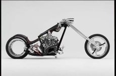
you can get the hub-less wheels made if you have the coin too, for memory it was ~$US20k for the ones
Billy Zane used on his custom hub-less chopper builds->

bikes.jpg

they are basically a GIANT sealed bearing with a tire on them

Best i would manage is a roller blade wheel effort like posted previous page, i would try to source a mag wheel though as you elude to Mike
maybe something off a 250cc bike, their wheel size is pretty close to what my crusier uses on the ass end now...
I have even heard people fitting motorcycle tries to these 20x4.25in rims on another forum.

Be cool to see a few more powered bicycles with hub-less wheelz anywayz, practical or not they are damn cool IMO...

KiM
 
Looking at these, I was reminded of a concept I had thrown together for a 'hubless' stand-up scooter - sorta a future version of the Goped ESR.... Used a high-speed hub motor inside the rim. Of course, it would only go as fast as the max rpm of the hub motor......


GopedADAM01.jpg


GopedEVE03.jpg


GopedEVE04.jpg


GopedADAM02.jpg
 
Back
Top