Stuck Troubleshooting LiFePO4 16-cell BMS

Regenpak

100 µW
Joined
Oct 9, 2012
Messages
7
A good friend of mine is an unlucky critter. Building his e-bike with a kit from a German supplier he blew up his power pack. After replacing borked cell it transpired that his BMS was kaput as well. With lots of effort replaced that one with another one that gave about 10 miles before it quit. Third BMS charges fine but refuses to output any power even though the cells are fine. All over the board, but OK. If 3.37 to 3.75 volts can be considered OK...

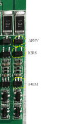
Anyhoo, the controller in question is a Lipopower.de SB70. After delivery this vendor stayed mum on any useful information, and the Google translated enclosed document (yes, from chinese to english) is not very useful anyway. The circuit is similar to the circuit shown here. However, the devices used are different and I couldn't find anything at all about them. There's a device marked R2RZ (SOT23-5) and one with G4EZ (SOT23-6). These must be similar to AP431 zener and NCP800 controller, but those are marked completely different. And there is a SOT23-3 transistor marked PD, which maybe could be a P-channel MOSFET BSS84L, used for cell balancing.

Now I hate testing stuff on my workbench with a lot of energy in it, in this case 16 LiFePO4 15Ah cells, without knowing all the details. So the question is: does someone have a schematic of this BMS?
 

Attachments

  • IMGP9952.jpg
    IMGP9952.jpg
    278.2 KB · Views: 1,997
Figured it out. Drew a schematic based on NCP800. The bottom chip is connected to overcurrent resistor and is in panic mode. Guess it's blown up somehow. But it gets better: I got a schematic from Lipopower for a similar device and it's practically identical, albeit for only 12 cells and 30 amps. The monitoring chip (G4EZ marking) is an S8261 from Seiko. Now I only need a replacement... The "PD" device indeed is a P-channel MOSFET BSS84. The third chip, marked R2RZ and used for battery balancing, is an S8211D.
 
over current mode on a single channel does not make sense. do you mean over voltage?

the comparator is turned on to drive an opto isolator or does it drive a signal line that goes up to the charging mosfet?

on some of the BMS i see, the comparator drives an npn transistor that drives the signal line through a resistor and the resistor changes from the top of the pack to the bottom to protect the HVC control transistor at the bottom from the high voltage of the top of the pack. i assume the current on the signal line is monitored by another transistor at the base of the pack controlling the charging mosfet.

do you have digital control of the shunt transistor so it is a mosfet? i thought the shunt transistors were npn transistors in all cases except for digital controls.
 
Interesting, I have another BMS (from GBS Systems) that uses the S8261 SMD marked as G4EM (pinouts match) - it also drives the overcharge opto through a E1325 SMD transistor - the overcharge is set at 4.35V, which is waaaaaay too high for Lifepo4 - There was a few badly overcharged thundersky cells that these were bolted to (sigh).

I ended up modifying the circuit so that the 431 shunt triggered the transistor and OC opto when it started bypassing, with the S8261 as a last resort. Not sure the why of this component selection, someone must have thought it a good idea once, and everyone has duplicated it ad nauseum. Maybe someone copied a BMS for the wrong chemistry?
 
@dnmum: No, it's overcurrent, or overload. The sense resistor is connected to the bottom S8261 but when it shuts down it takes the whole string of opto's with it thus switching off the DO (discharge) MOSFET. There seems to be an issue with the chip going in shutdown mode which I don't understand. The datasheet is not very clear what to do about it, it sez to charge the cell but I already did that. Also, why are none of the other S8261s not in panic mode then? Really weird...

@heathyoung: according to the same datasheet, the V(CU) should be 3.90 V. The SMD marking (which I found explained in another Seiko datasheet) is three letters product type, one letter production month. Your G4EM should be identical to my G4EZ, just from a different batch. The full model number should in both cases be S-8261ACEMD-G4ET2G. In this document the device marking is not explained, in an older version it is.
 
Slowly getting somewhere. I swapped a S8261 from higher up with the one connected to the current sense resistor and it works. Only now the opto's gone phut. Diode almost short circuit. This I don't get. First of all, the diodes in those things are sturdy and will withstand currents up to 0.1A. ESD maybe, but still. While I haven't observed ESD guidelines I do have an ESD safe workbench and chair. Maybe I fried it with heat. Really weird. But I have replacement PC817s. These things are generic, no sweat.

Now's waiting for a replacement chip, then I can kick that stack out the door. After I've balanced the cells because they're all over the place. Prolly because the previous BMS's were crap. This I must admit: the Lipopower unit is technically OK. I now know how it works, actually got support from Germany (I'm in Amsterdam) and it's got no black goo all over it. Which could be a solution, because goo (from the previous one) can be scraped off... Hmmmm...
 
From Lipopower my friend received a scrap board with more than enough S8261s and opto's to fix the BMS. It works now. The cells are all over the place so balancing is needed.

Lessons learned: LiFePO4 is not as maintenance-free as you'd like and troubleshooting other people's projects is not as fun as fixing your own...
 
Hi. I've developed a product of bestechpower company. HCX-D166 19s 40A. After a period of use it, tow piece is damaged and I would like to change them.
R2RS and AFNV.
Can someone tell me what the pieces are and how to find them. I will be happy if you send me a datasheet link of these parts.Thank you
 
so this guy regenpack started out saying his BMS was trash and had all this info that it was trash and then at the end he said there is nothing wrong with it. i did not understand why he thought it was dead or why he said that initially since there was no evidence of any testing..........

this last guy now is asking how to find parts which are only available to manufacturers of the BMSs.

can you explain what parts are dead on which channel and how you determined that they are defective?
 
Thank you for your attention. These parts were burned. Of course there are other parts that I bought them. I do not know how it works for a channel. If anyone has knowledge of circuit design and components of it, I would be honored explain me. Thank you
 
I do not have a good camera to take a picture of it.But that is just like the photo below. The only difference between the three pieces s8261(GDTD) and s8241(G3PJ) and AFYV transistor.
in my board G4EM , R2RS and AFNV transistor.
 
4.20V vs 4.28V.jpg
k1jahan said:
I do not have a good camera to take a picture of it.But that is just like the photo below. The only difference between the three pieces s8261(GDTD) and s8241(G3PJ) and AFYV transistor.
in my board G4EM , R2RS and AFNV transistor.
 
the spots where you circled are not part of the balancing network and would not have the G4 or R2 comparators present there in the control circuit for the output mosfets.

did you measure the resistors to confirm the 682 and 685 resistor values? 6.8kR versus 6.8MR and i assume you make the comment about missing because you expect they should have identical parts on each?
 
No, I did not specify them. I have downloaded this photo. I have a better picture
 

Attachments

  • k1.rar
    6.1 MB · Views: 61
nope, cannot see it. you can just take a VGA picture with your digital camera and load it to the disk and then upload it to the thread using 'upload attachment' at the bottom of the page when you enter the text.
 
Back
Top