catalystTGJ
1 mW
Hello folks,
Newbie here. I've been reading quite a bit on this site and I have to say that this is one awesome outfit! Thanks for the great postings! I've learned a lot so far and I'm sure I've barely scratched the surface here.
I have an unusual setup i think. At least in the sense that I don't see a whole lot of folks discussing the kind of hardware that i have. I do see discussions about Ananda controllers, but it seems fairly limited. I suppose this has something to do with market penetration in the US of the ebike that I have.
The setup is a chinese sourced ebike (Later, I'll find a pic of my ebike on-line and post it here.). I purchased the bike locally from an ebike dealer (rmartinbikes.com). The bike has an extended rear fork allowing for a vertical battery compartment under the seat. It is a full suspension, heavy steel frame with a large front fork, disc brakes on front & back. The bike has a rear wheel 250watt brushless motor with a 6 sprocket cassette. Originally there was only a single chain ring on the front making the bike a 6 speed only. I upgraded this with a much nicer richey 3 ring setup. This required adding a front derailleur since the bike didn't have one to begin with. This created interference problems with the battery pack. I had to lift the battery box to make room for the bottom pull mechanism of the derailleur. The main reason for all the mechanical modding was simply that I wanted more low end as this bike is very very heavy; nearly 100lbs loaded (rear rack hauling a laptop), and it was too hard to do pedal only with only a front 38or40 tooth ring. The three ring had to be a square taper connection, so i didn't have too many choices, (unfortunately due to the overall width of the BB, cartridge upgrade was not possible here.) but i managed to find a setup that gave me a nice variety, so I ended up with a much lower gear, and a few teeth more on the large ring. All of this was awesome. Coupled with the 36 volt Ananda brand controller, I could reach speeds up to 28mph downhill. On a flat it was more around 18 to 19mph. Not too bad. A lot better than my averages on a regular un-powered bike.
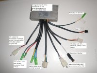
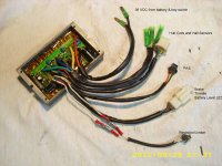
I've had a look around in both the controller and the motor and here's what i can say about each of them. The motor is of the type where they used the little wooden sticks to separate the sections of the motor. (sorry for the lack of proper motor lingo here), it is fairly basic, so i think it's probably a fairly low quality device. I don't see many markings on the outside of it to identify who the manufacturer actually is, so that's about all i can say there. It is a typical brushless in its basic wiring. The controller made by Ananda, and is a 6 FET config. After removing all the potting material, here are the markings that i could identify on each of the major components inside it:
ICs:
Ananda 2 - this chip is in the center of the board, and has a code, but i forgot to write this one down. I know this is basically the PCM controller, the meat and potatoes of the timing of the phases for the motor.
Comparator - This one I looked up but i have forgotten the code that was on it. It is a TI brand chip. I'm sure this is the logic chip for the hall sensors. There seems to be quite a few resistors between this chip and the hall sensor cables.
1) LM317T CCOA9W MAR452 ST brand < curious about this one. What would this be for?
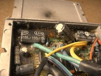
Caps: (cylinder style)
1) 63V470uF 105c LSHC brand
1) 50v0.47uF 105c LSHC brand
1) 25v10uF 105c LSHC brand
1) 16v100uF 105c Chana brand
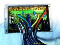
FETs:
6 total, but marking varied a little. 2 were not of the same maker.
2) P75NF75 CCOC7 MAR522
1) P75NF75 HW23C 6 KOR452
1) P75NF75 HW22W 6 KOR452
2) P75NF75 HW229 6 KOR452
I imagine folks who are more familiar with electronics know what most of these components are doing in this controller, which i am personally not all that knowledgeable in this area, though i probably know more about it than the average person.
At any rate, based on the following four factors, I decided to over-volt this controller to 48 volts by simply adding another 12volt SLA in series:
1.) The knowledge of experiences of others gained from this site. Extremely helpful in pushing me over the edge to trying this out.
2.) The manufacturer site for the controller, though not certain, almost implies that they may have simply one brushless controller that by design handles the entire range of 12 to 48 volt applications. The pic of the controller on their site looked identical to mine, though this was an external pic only, and in no way was a good verification of more than a similar casing being used.
3.) I have an identical spare motor controller that i purchased from the dealer that sold me the ebike. I bought this controller for troubleshooting purposes when i believed that i had a major hardware failure and thought that the controller was blown. After replacing the controller and still having the same problem i went on to believe that it might be the motor's hall sensors or a throttle control problem. I had to put the project down for a while, busy with work, but when i got back to the bike, i disassembled the battery box and discovered that one of the battery leads had become partially severed from bouncing up and down inside the battery box too much and ultimately crimping the wire between the battery casing and the inside uneven edges of the box itself! This was restricting current flow badly, but not completely which was causing the motor to be unable to deliver enough power to push the bike with a rider on it even at full throttle.
4.) Reviewing the controller's major components and realizing that the FETs are rated for 75volt and paralleled as well. All of this suggested that the manufacturer probably overbuilt this thing to handle some abuse or to, in fact, handle 48 volt operation by design.
At any rate, after reading about the many successes of others, I went for it! As a result of the battery lead damage with the original battery pack, I had to rebuild a new pack. I used the 12 volt 7AH SLA style for space restriction mostly. I had actually bought 6 of these batteries many moons ago in the hopes that either A, I would eventually run 3s2p or B, 6s to get to 72 volt operation. I was able to use a flat piece of aluminum, and double sided surface mounting tape to create the needed support to get the new batteries into the same location of the original pack. They are much more secure than the previous battery box. The only major detail left is protecting the terminals from water in the event of rain.
My commute is fairly short. I only need about an 8 mile range for capacity. I mainly use my ebike for going to work and back which is only 4 miles from the house. 3 grocery stores around my house are all also within a 4 mile radius, so those places are close enough for the lower 7AH. The original batteries were supposedly 12AH, BUT... they are smaller in size compared to the 7AH batteries that I'm using, and only available directly from China as far as I can tell. I find it hard to believe that these batteries are truly 12AH considering their relative size to the 7AH batteries.
I hooked up everything normally, and tested the new pack in the 36 volt configuration. All was well, I then hooked in the extra battery. After that i tested the motor under no load with full throttle and could tell immediately that i had much higher rpms! I then took it out for a test spin around the block, and wow! What a thrill. Now I was reaching 20+ mph without pedaling at all! Very nice! I then charged up the batteries overnight. I had to split the pack and charge three with my original charger, and then the one with a 12 volt charger from an old electric weed eater that broke on me. This charger was designed to charge the exact same SLA battery in that weed eater, so i wasn't too worried about any problems there. The next morning I rode to work on this new machine, and wow! I can now make the trip in about 15 minutes, and that is without trying real hard. I'm a little out of shape right now, since i have been off the bike for considerable amount of time, so i expect that after a few months I'm going to lower that time at least by a minute or so. That's only a couple minutes over the amount of time it would take me to make the same trip in a car!
Also, I have not detected any major heat change on the motor or the controller since this over-volt experiment. Also, I've read that whatever wattage a motor is rated for, it is very likely that it can be doubled without killing the motor.
Now my question for folks here is this... based on the information that i have on this controller, does it look reasonable that this controller might be able to handle 60 volts? Could i get away with that, given the FETs are 75volt? or is there a weak link somewhere else? I understand that there is a low voltage side to the controller that handles the pcm and the sensors and what not, so I'm just wondering based on the specs that I've provided about the components on this controller, does this controller look like it might handle 60, or an absolute no way? I''m very curious but i don't want to smoke the thing just a day after I got it all working!
Any advice would be great!
Later on, I really want to go to 72 volt, but will go all out and upgrade the motor, controller, and batteries at that time. I'm likely to use a 408 and a 72v 35a controller, and the A123 dewalt formula for the batteries. This sounds downright awesome to me! Also, my future vehicle purchase (in 2009) will be a v1 from venture vehicles. Check it out at flytheroad.com
Thanks in advance!
Newbie here. I've been reading quite a bit on this site and I have to say that this is one awesome outfit! Thanks for the great postings! I've learned a lot so far and I'm sure I've barely scratched the surface here.
I have an unusual setup i think. At least in the sense that I don't see a whole lot of folks discussing the kind of hardware that i have. I do see discussions about Ananda controllers, but it seems fairly limited. I suppose this has something to do with market penetration in the US of the ebike that I have.
The setup is a chinese sourced ebike (Later, I'll find a pic of my ebike on-line and post it here.). I purchased the bike locally from an ebike dealer (rmartinbikes.com). The bike has an extended rear fork allowing for a vertical battery compartment under the seat. It is a full suspension, heavy steel frame with a large front fork, disc brakes on front & back. The bike has a rear wheel 250watt brushless motor with a 6 sprocket cassette. Originally there was only a single chain ring on the front making the bike a 6 speed only. I upgraded this with a much nicer richey 3 ring setup. This required adding a front derailleur since the bike didn't have one to begin with. This created interference problems with the battery pack. I had to lift the battery box to make room for the bottom pull mechanism of the derailleur. The main reason for all the mechanical modding was simply that I wanted more low end as this bike is very very heavy; nearly 100lbs loaded (rear rack hauling a laptop), and it was too hard to do pedal only with only a front 38or40 tooth ring. The three ring had to be a square taper connection, so i didn't have too many choices, (unfortunately due to the overall width of the BB, cartridge upgrade was not possible here.) but i managed to find a setup that gave me a nice variety, so I ended up with a much lower gear, and a few teeth more on the large ring. All of this was awesome. Coupled with the 36 volt Ananda brand controller, I could reach speeds up to 28mph downhill. On a flat it was more around 18 to 19mph. Not too bad. A lot better than my averages on a regular un-powered bike.
I've had a look around in both the controller and the motor and here's what i can say about each of them. The motor is of the type where they used the little wooden sticks to separate the sections of the motor. (sorry for the lack of proper motor lingo here), it is fairly basic, so i think it's probably a fairly low quality device. I don't see many markings on the outside of it to identify who the manufacturer actually is, so that's about all i can say there. It is a typical brushless in its basic wiring. The controller made by Ananda, and is a 6 FET config. After removing all the potting material, here are the markings that i could identify on each of the major components inside it:
ICs:
Ananda 2 - this chip is in the center of the board, and has a code, but i forgot to write this one down. I know this is basically the PCM controller, the meat and potatoes of the timing of the phases for the motor.
Comparator - This one I looked up but i have forgotten the code that was on it. It is a TI brand chip. I'm sure this is the logic chip for the hall sensors. There seems to be quite a few resistors between this chip and the hall sensor cables.
1) LM317T CCOA9W MAR452 ST brand < curious about this one. What would this be for?
Caps: (cylinder style)
1) 63V470uF 105c LSHC brand
1) 50v0.47uF 105c LSHC brand
1) 25v10uF 105c LSHC brand
1) 16v100uF 105c Chana brand
FETs:
6 total, but marking varied a little. 2 were not of the same maker.
2) P75NF75 CCOC7 MAR522
1) P75NF75 HW23C 6 KOR452
1) P75NF75 HW22W 6 KOR452
2) P75NF75 HW229 6 KOR452
I imagine folks who are more familiar with electronics know what most of these components are doing in this controller, which i am personally not all that knowledgeable in this area, though i probably know more about it than the average person.
At any rate, based on the following four factors, I decided to over-volt this controller to 48 volts by simply adding another 12volt SLA in series:
1.) The knowledge of experiences of others gained from this site. Extremely helpful in pushing me over the edge to trying this out.
2.) The manufacturer site for the controller, though not certain, almost implies that they may have simply one brushless controller that by design handles the entire range of 12 to 48 volt applications. The pic of the controller on their site looked identical to mine, though this was an external pic only, and in no way was a good verification of more than a similar casing being used.
3.) I have an identical spare motor controller that i purchased from the dealer that sold me the ebike. I bought this controller for troubleshooting purposes when i believed that i had a major hardware failure and thought that the controller was blown. After replacing the controller and still having the same problem i went on to believe that it might be the motor's hall sensors or a throttle control problem. I had to put the project down for a while, busy with work, but when i got back to the bike, i disassembled the battery box and discovered that one of the battery leads had become partially severed from bouncing up and down inside the battery box too much and ultimately crimping the wire between the battery casing and the inside uneven edges of the box itself! This was restricting current flow badly, but not completely which was causing the motor to be unable to deliver enough power to push the bike with a rider on it even at full throttle.
4.) Reviewing the controller's major components and realizing that the FETs are rated for 75volt and paralleled as well. All of this suggested that the manufacturer probably overbuilt this thing to handle some abuse or to, in fact, handle 48 volt operation by design.
At any rate, after reading about the many successes of others, I went for it! As a result of the battery lead damage with the original battery pack, I had to rebuild a new pack. I used the 12 volt 7AH SLA style for space restriction mostly. I had actually bought 6 of these batteries many moons ago in the hopes that either A, I would eventually run 3s2p or B, 6s to get to 72 volt operation. I was able to use a flat piece of aluminum, and double sided surface mounting tape to create the needed support to get the new batteries into the same location of the original pack. They are much more secure than the previous battery box. The only major detail left is protecting the terminals from water in the event of rain.
My commute is fairly short. I only need about an 8 mile range for capacity. I mainly use my ebike for going to work and back which is only 4 miles from the house. 3 grocery stores around my house are all also within a 4 mile radius, so those places are close enough for the lower 7AH. The original batteries were supposedly 12AH, BUT... they are smaller in size compared to the 7AH batteries that I'm using, and only available directly from China as far as I can tell. I find it hard to believe that these batteries are truly 12AH considering their relative size to the 7AH batteries.
I hooked up everything normally, and tested the new pack in the 36 volt configuration. All was well, I then hooked in the extra battery. After that i tested the motor under no load with full throttle and could tell immediately that i had much higher rpms! I then took it out for a test spin around the block, and wow! What a thrill. Now I was reaching 20+ mph without pedaling at all! Very nice! I then charged up the batteries overnight. I had to split the pack and charge three with my original charger, and then the one with a 12 volt charger from an old electric weed eater that broke on me. This charger was designed to charge the exact same SLA battery in that weed eater, so i wasn't too worried about any problems there. The next morning I rode to work on this new machine, and wow! I can now make the trip in about 15 minutes, and that is without trying real hard. I'm a little out of shape right now, since i have been off the bike for considerable amount of time, so i expect that after a few months I'm going to lower that time at least by a minute or so. That's only a couple minutes over the amount of time it would take me to make the same trip in a car!
Also, I have not detected any major heat change on the motor or the controller since this over-volt experiment. Also, I've read that whatever wattage a motor is rated for, it is very likely that it can be doubled without killing the motor.
Now my question for folks here is this... based on the information that i have on this controller, does it look reasonable that this controller might be able to handle 60 volts? Could i get away with that, given the FETs are 75volt? or is there a weak link somewhere else? I understand that there is a low voltage side to the controller that handles the pcm and the sensors and what not, so I'm just wondering based on the specs that I've provided about the components on this controller, does this controller look like it might handle 60, or an absolute no way? I''m very curious but i don't want to smoke the thing just a day after I got it all working!
Any advice would be great!
Later on, I really want to go to 72 volt, but will go all out and upgrade the motor, controller, and batteries at that time. I'm likely to use a 408 and a 72v 35a controller, and the A123 dewalt formula for the batteries. This sounds downright awesome to me! Also, my future vehicle purchase (in 2009) will be a v1 from venture vehicles. Check it out at flytheroad.com
Thanks in advance!
")