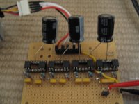
Switched capacitor balancer tests

The thing that most don't get about these switched cap/charge pump-type of balancers is that it is meaningless to talk in terms of charge cycles, as it relates to balancing. Standard shunt-based BMS designs don't do balancing until it is time to charge. The balancing logic then tries to bring the cells back into balance at the end of the charge cycle. The idea behind the switched cap scheme is that the circuits are always working, so the cells should always be pretty close. These aren't meant to be hooked up during a charge, and expected to bring the cells back into balance quickly.

Richard and I played around with a couple designs based on an LM2663 chip, back a couple years ago, but back then I didn't really "get it" yet and was thinking in terms of a "quick balancer", and thought the current transfer limit of around 200mA, wasn't going to cut it. I may have to revisit this, at some point, because 200mA is more than enough transfer current, I now think, for an "always on" type of system. Hmmm, now where did I put that schematic file... :roll: :mrgreen:

-- Gary
 
A switched cap balancer works rather poorly on LiFePO cells that are just sitting in the middle of their discharge curve. The cells are at pretty much the same voltage even though their state-of-charge is rather different. The swicthed cap balancer equalizes the cell voltage and not the true state-of-charge.

The switched cap balancer works best when used during pack charge or discharge when there is some effective load on the cells that causes their voltages to spread. I was pretty amazed at how well it worked getting an empty and fully charged cell in series to end up fully charged and balanced. I think that it will work rather well at keeping a pack from becoming unbalanced if it is run when the pack is in use and charging. It will probably not be very good at initializing a new pack (particularly if it is large Ah).

I think that it can be designed so that the load on the cells is pretty much zero when not being clocked. Also it is fairly tolerant of component failures when idle or not being clocked... A shorted FET or cap won't cause it to drain a cell during storage. Once can't say that for a resistive balancer.
 
And it can also be "double capped" if you want to get really nutty ...

cap_balance_5.jpg


reference
 
I also played around with a circuit that charged the cap across two cells, and then discharged it across one cell. This radically increased the balance current (to where it rivaled inductive systems). The effects of dumping a capacitor charged to 7V across a 3.5V cell may not be good. But the cell ESR is much lower than the cap/FET ESR, so it may not be bad either...
 
texaspyro said:
I also played around with a circuit that charged the cap across two cells, and then discharged it across one cell. This radically increased the balance current (to where it rivaled inductive systems). The effects of dumping a capacitor charged to 7V across a 3.5V cell may not be good. But the cell ESR is much lower than the cap/FET ESR, so it may not be bad either...

Hi,

I refer you to the earlier discussion about energy loss when charging and discharging caps. That would be very inefficient. It doesn't matter whether the R is in the caps, the FETs or the cells; if you have large voltage swings on the caps, a lot of the energy you are trying to shuttle around will be wasted.

Nick
 
The only energy "lost" in charging the caps is the initial bit of energy it takes to charge the caps from 0 to the lowest cell voltage. That energy will never be recovered since the caps are never discharged below that value.

Cap charging and discharging is not an inherently inefficient thing. Look at the LM2662 data sheet... it is around 90% efficient.

The idea of charging the caps to Vcell*2 then discharging to Vcell depends upon the cap ESR/FET Rds to act as a current limiter so the the cell can clamp the voltage that it sees. Otherwise the cell would see pulses higher than Vmax_charge_voltage. It remains to be seen how well that would work... it might still overvolt the cell. Anyway, it is probably not a good idea. The implementation leaves a lot to be desired.
 
texaspyro said:
Cap charging and discharging is not an inherently inefficient thing.

Its only efficient in certain circumstances, and one indicator is how much the voltage is changing. You also have to consider that the current flowing in and out has to pass through various resistances.

Charging a cap to 2* Vcell and then discharging it into Vcell will be very wasteful of energy. For a start you will be taking charge Q and moving it to half the voltage, so you have dropped its energy by half. Then you have inevitable I^2R losses which will take it down further.

That's an extreme case, but you can see the point.

Nick
 
Knuckles said:
Not my drawing ... found it on-line.

That drawing came from a post on my web site:

http://b2600ev.org/battery-experimentation-part-2.html

I conducted a switched capacitor battery balancing experiment on some small cells. The circuit was just for the purpose of testing the concept between two cells, and as such the gate drive method was sufficient.

I thought it was an interesting idea but my conclusion was that it was not practical because as some of you observed, as the cell voltages get close together hardly any charge is transferred and with these cells they can be almost the same voltage but with different state of charge. Also, it seems like it would require a lot of parts per cell. I came up with 4 mosfets and a gate driver per cell. Perhaps you could find some integrated switch part to replace the mosfets.
 
Tiberius said:
Its only efficient in certain circumstances, and one indicator is how much the voltage is changing. You also have to consider that the current flowing in and out has to pass through various resistances.

Charging a cap to 2* Vcell and then discharging it into Vcell will be very wasteful of energy. For a start you will be taking charge Q and moving it to half the voltage, so you have dropped its energy by half. Then you have inevitable I^2R losses which will take it down further.

That's an extreme case, but you can see the point.

Nick


Totally agreed Nick. The advantage of being able to add to the low cells (rather than dropping all high cells to the lowest level resistively) though saves a boat load of energy from a system perspective, dispite substantial losses from cap voltage drop in the charge transfer (because while the amount of charge stays roughly constant, the potental in that charge drops by a lot during the storage and return process).
 
Don't get me wrong; I'm not dissing the use of flying capacitor balancing. Its a whole lot better than resistive balancing and its relatively simple. Best of all it doesn't require any control system. I just want to counter the impression that its 100% efficient. I don't want to fall out with anyone; I'm just trying to contribute a technical point.

I don't think I'd want one running all the time on a battery pack, but running it all the time the pack was charging would make sense.

Nick
 
I got around to building a 4 cell test circuit and did some component cost analysis. The test circuit uses the capacitor isolated gate drives. Works very well. Nice and clean waveforms. It supports separate clocks for the P channel and N channels FETs so that you can totally eliminate shoot-trough on the FETs when switching at high freqs. I have been clocking it off a signal generator. I now need to code up a gate drive chip that makes non-overlapping clocks so that I can run it at higher freqs without MOSFET shoot-through and optimize the capacitor values for maximum charge transfer.

When the fets are not being clocked. there is no drain on the cells. Also, if one of the two FETs on a cell shorts out there is still no drain.

Now to the nitty gritty. Each cell requires a P-channel mosfet and an N-channel mosfet. You can get both of these in a single SO-8 package. Each mosfet requires a gate isolation cap, a gate-source resistor to keep the fet off when it is not in use, and a diode (preferably a zener) to provide DC-restoration and gate protection, and a electrolytic capacitor (or two).

With some judicious shopping on the surplus market the cost per celll is (probably double if bought in quantity from distributors, double again for small quantities):

MOSFETs $0.13 - SI4050DY dual mosfet chip
Resistor $0.01 - 100K
Zener $0.02 - 6.8V
Gate cap $0.05 - 0.1 uF, rated above the pack voltage.
Big cap $0.10 - 500uF-5000uF, 6.3V-10V
PC board $0.12 - approx 1 square inch/cell, (doable on sided no holes drilled PCB)
Gate drive: $ 1.00 - ATTINY13 and 78L05, one per system (these can be supplied from a microcontroller based total BMS system)

Works out to about $0.50 per cell. If you want to use a dual tier capacitor structure for greater balancing capacity, you add another big cap per cell (OK, you can actually use N-1 caps per cell, 2N-3 caps for dual tier). Construction wise would work very well with 8 cell boards that can be cascaded up to around 32 cells. Larger arrays would probably require a $1.00 mosfet driver chip on the output of the clock generator.

balancer.jpg
 
I coded up an ATTINY13A micro to generate the non-overlapping clocks for the P and N channel MOSFETs. It works amazingly well. Switching at 100 kHz the shoot-through current was well under 100 microamps (mainly due to inductance/capacitance in the wiring, and not actual shoot-through. I have it set for 1 microsecond of dead time which is a bit excessive. I'll probably trim that down and also drop the clock rate on the micro to cut its power consumption to under 1 mA.

Now I can play with different capacitors/switching freqs and see what combo delivers the most bang for the buck.


While I had the TINY13 development hardware fired up, I also coded up a timing track simulator for the Tektronix Y-T chart recorder used in the 1502 and 1503 time domain reflectometers (TDR). The YT chart recorder uses rolls of paper with a timing track punched along one edge. The paper is obsolete and basically unobtainable ($40-$50 a roll from Germany), but is otherwise identical to standard $1/roll ECG paper. Without the holes in the paper, the chart recorder wont run. With my little mod-chip it works great with the $1 paper. :D
 
Fantastic!

Want some PCB's made up for free?

Draw it up, email me the file, and I will CNC some board for you and mail them for free. I've got a few hundred 4"x8" FR4 copper clad boards, and all the needed tooling for my CNC just sitting collecting dust, waiting for something slick to be made into. :)
 
Many thanks, but not sure when I'll be ready to fab some boards...

I modified my clock generator code so that I can feed it from a signal generator. Makes it easy to test at different clock freqs.

I dug out one of my Tektronix AM503S current probe systems and started probing around the board. I was seeing some pretty good current transfers in the balance leads to the 4S1P A123 pack... like well over 1 mA/mV (and that is with some rather skanky MOSFETs that have over 0.5 ohms Rds. I need to unbalance some cells in the pack and see what that looks like.

I did notice some rather large (500 mA) very short (50 nsec) current spikes when the FET clocks change. It looked like shoot-through, but was still there when I pulled the fets. It looks like the MOSFET gate driver chip that I am using is coupling into the ground bus... My perf board layout leaves a LOT to be desired. At least the spikes are symmetrical + and - spikes... they're not draining the pack.
 
excuse my lack of knowledge on this topic
but...... if you connect all cells in a pack into parallel ( take out of series) will they automatically balance themselves, so that they all land up with exact same voltage?
 
Yes, but if they are not rather close in voltage before you parallel them, they can draw lots of current and damage themselves before the state-of-charge equalizes. Also, rewiring the pack to all parallel connections before charging is usually not practical. And your charger will have to be able to supply huge amounts of current to charge them in a reasonable amount of time.
 
Any chance of reviving this thread, this type of balancing looks like it has a lot going for it over the other types
and it's stuck on the bottom shelf.

Looking at the basic diagrams knuckles researched, good work.
and the associated research, i thought i'd knock together a relay version.
4dpdt relays are a couple of dollars in the 2A signal range and just a 2 relays simple set up could balance an 8S set up.

I was thinking of using signal relays, even though they are electromechanical, for the simplicity, looking at the life span
say about 3 million mechanical operations and much more electrical op's when switching low loads and volts.
Arguments over efficiencies seems trivial here, as previously found and resistive aspects of losses in circuit might be advantantageous in extending contact life and time constant stability.

I'm hoping for really low switching speeds at around 1 sec cycling, charging = 2 time constants, discharge similar using a simple timer, with presets for freq and duty, to switch the coils. At this slow speed hoping approx 1000 hrs or more MTBF.
The trade of of switching time vs charge delivered is a real headache. 2 time constants around 0.5S, so 1tc = 0.25S.

I'm want to use a cell log's alarm switching output to control the oscillator so it switches on the differential alarm.
With cell differential of say 200mV,then if want to initially switching 2A then R = 0.2/2 = .1ohm, neglecting cell resistances.
Was considering the resistance of a series quick blow fuse would drop the current slightly and helping some in stablising the tc and increase contact life and save contacts in a short circuit event.
Main capacitors = .25/approx 0.13, nearest 2.2F, .25/2.2 = 0.113 ohms, close enough.
Just need super caps that likes switching an amp a couple of million times.
Upper tier caps are more difficult in assessment, but indicted they are lower Farad than the 1st tier.

Any one interested and i'm sure i've gone of in some places, any input would be good.
 
I don't think that using mechanical relays and large value caps will work very well at all. Plus, most cheap supercaps have hideous ESR's. Low ESR supercaps can be very expsnsive.
 
Hi Tex,

Was thinking that 1F 5.5v caps are around $1 these days, in parallel the esr is halved, could be >40 mohm @ 2F
4pdt relays with 50-100 mohm are a $1 OR 2. 1x 555timer switching the set up is hellishly simple.
My pack is switched to parallel balancing when not in use, only want to use it during charge and run,
initiated from celllog diff' alarms.
If it lasts as long as a the pack would be good. Toss it with the pack or renew the components.

Though your not wrong, if your kit is less than a $1, can it switch amps :?:
I want my A123 20AH @ 2C, do you reckon it could handle this :?:
 
Most of those cheap supercaps have an effective ESR measured in 10's to 1000's of ohms. They are designed to supply a few microamps to back up a memory or clock chip.
 
This setup looks brillant. As I understand it, it works with any chemistry, any cell count, charger on or off, but has a very low balance "current". I want some of this, could someone do a tutorial and some schematics/part lists? I would build one for 16s and report.
 
texaspyro said:
Most of those cheap supercaps have an effective ESR measured in 10's to 1000's of ohms. They are designed to supply a few microamps to back up a memory or clock chip.

Most i am looking at are around 50 mohms, different duty, not for back up,
so when indicating 40 mohm for 2 in parallel, i'm being generous.
Admitedly esr does go to crap in old age/long cycling life, stressed a million times, time to ditch.

Yep capacitor balancing seems like a good idea, not sure of my idea, but generally speaking, thinking under utililised.
If someone could come up with a selective version, selectively fast balance the most differential pairs, that would be the ducks nuts :mrgreen:
 
Initial tests on 2 neighbouring cells, switching @ 5 sec on 5 sec off,11F &100mV diff, 400mA charge, 600mA discharge, :D obviously got to much series resistance, had a 22F in the junk box, sacralige :roll: and it was only 2.5V, so bought another anyway so double series ESR, but indicating fairly low ESR's if 0.6A is flowing and a good indication of what value of what dual layer cap's actually need and not far off mark with what was envisaged, its just a lash up at the moment going to shorten cabling by 90% and better connections to batts etc.

Work on the duty cycle could be interesting, what is best duty cycle hmmm that's going to be complicated, expect it needs to be different on differing parts of the bat charge/discharge curve, does the system need feedback is it easy to do :?:
 
Pretty simple set up got 4 x 4dpdt on back of a vero, fudged togethe, just got 2 channels on 1 of the relays going for evaluation and a timer board pulsing the coils, still have to mod for variable freq and duty.
Final set up will hopefully do a 2 x 8 cell when the caps are fitted.
Hooked onto 20AH, 8 pouch cell at the moment, ticking away like a swiss watch :D .
 
Back
Top