Test Results of my Schwinn AL1020

The7

10 kW
Joined
Jul 11, 2007
Messages
761
Location
Vancouver
Some Test Data on my Schwinn AL1020 done today.

For old test results and photos please see:
http://endless-sphere.com/forums/viewtopic.php?t=1611

I dc = Battery Current

I y = Current to Yellow Phase of Motor
I b = Current to Blue Phase of Motor
I g = Current to Green Phase of Motor

V yb = Voltage be tween Yellow Phase and Blue Phase
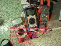
At 24 V Battery

1) No-Load Speed at Full Throttle = 30 km/h
I dc = 1.20 A
I y = 0.590 A
V yb = 18.57 V

Then Input Power = 24X 1.20 = 28.8 W
If V yb is sinusoidal,
then its peak value will be 18.57 X 1.414 = 26.3 V which would be approximately equal to the battery voltage at full throtle.


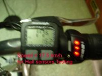
2) No-load Speed at partial throttle = 20 km/h
I dc = 0.72 A
I y = 0.574 A
V yb = 15.36 V

Then Input Power = 24X 0.72 = 17.3 W


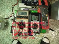
3) No-load Speed at partial throttle = 10 km/h
I dc = 0.34 A
I y = 0.474 A
V yb = 9.67 V

Then Input Power = 24X 0.34 = 8.2 W

More results of waveform will be coming with the aid of Oscilloscope.
 

Attachments

  • DSCN7189 copy.jpg
    DSCN7189 copy.jpg
    50.6 KB · Views: 4,286
  • DSCN7191 copy.jpg
    DSCN7191 copy.jpg
    54.6 KB · Views: 4,286
  • DSCN7190 copy.jpg
    DSCN7190 copy.jpg
    58.8 KB · Views: 4,286
Test to determine the Phase-sequence of the Hall Sensors.

For the Hall Sensor Connector:
V red-black = 5.07 V ( 5 Vdc Supply)
V yellow-black = 0.03 OR 4.97 V (Yellow Sensor Output)
V blue -black = 0.03 OR 5.06 V (Blue Sensor Output)
V green-black = 0.03 OR 5.06 V (Green Sensor Output)

Phase Sequence as observed from Oscilloscope is:
Yellow - Blue - Green.

At speed = 17.5 km/h,
Frequency = 156 Hz
 

Attachments

  • DSCN7196 copy.jpg
    DSCN7196 copy.jpg
    24.5 KB · Views: 4,258
Test to show the Output Waveforms:

An double winding transformer (110:10) is used for measuring the output waveforms to the scope.

Hy = Yellow Hall Sensor Waveform

Vyb = Output voltage bet yellow and blue

V y = Yellow Phase Voltage.

Phase Sequence is Y-B-G

V yb leads H y by 60 deg..
And V yb leads V y by 30 deg.

Then Vy will lead Hy by 30 deg.

The output waveforms look like a trapezoidal shape.
 

Attachments

  • DSCN7204 copy.jpg
    DSCN7204 copy.jpg
    39.4 KB · Views: 4,231
  • DSCN7203 copy.jpg
    DSCN7203 copy.jpg
    32 KB · Views: 4,231
  • DSCN7201 copy.jpg
    DSCN7201 copy.jpg
    31.1 KB · Views: 4,229
  • DSCN7200 copy.jpg
    DSCN7200 copy.jpg
    40 KB · Views: 4,230
  • DSCN7198 copy.jpg
    DSCN7198 copy.jpg
    36.3 KB · Views: 4,230
Output Voltage Vyb and No-load Speed.
 

Attachments

  • DSCN7217 copy.jpg
    DSCN7217 copy.jpg
    30.8 KB · Views: 4,205
  • DSCN7216 copy.jpg
    DSCN7216 copy.jpg
    34.2 KB · Views: 4,206
  • DSCN7214 copy.jpg
    DSCN7214 copy.jpg
    35.5 KB · Views: 4,204
  • DSCN7215 copy.jpg
    DSCN7215 copy.jpg
    32.8 KB · Views: 4,204
  • DSCN7213 copy.jpg
    DSCN7213 copy.jpg
    33 KB · Views: 4,205
Obsevations:

for my stock controller,
1) The 3 Hall Sonsors are placed 120 elect deg apart.
2) The phase sequence is yellow-blue-green. (Y-B-G).
3) The output voltage Vyb leads the Hall signal Hy by 60 elect deg.
4) The output voltage waveform is trapezoidal with PWM frequency of 35 kHz.


Questions:
1) Would other contollers using the same color code Y-B-G have the same phase sequence and phase hift?
2) Would the phase shift between the output voltage and the Hall signal be the same?
3) Does Xytle controller has the same phase sequence and phase shift as my stock controller?
Have any one tested this controller?

If yes, one could use other made to upgrade his stock controller.
If no, one will have great problems and pains to make it work.
 
Obsevations:

For my stock controller,
1) The 3 Hall Sonsors are placed 120 elect deg apart.
2) The phase sequence is yellow-blue-green. (Y-B-G).
3) The output voltage Vyb leads the Hall signal Hy by 60 elect deg.
4) The output voltage waveform is trapezoidal with PWM frequency of 35 kHz.


Questions:
1) Would contollers using the same color code Y-B-G have the same phase sequence and phase hift?
2) Would the phase shift between the output voltage and the Hall signal be the same?
3) Does Xytle controller has the same phase sequence and phase shift as my stock controller?
Have any one tested this controller?

If yes, one could use other made to upgrade the stock controller.
If no, one will have great problems and pains to make it work.
 
In my experience, the phases are usually labeled as U, V and W. Different mfrs. use different colors for those. Everybody uses 120 degree phase shift, of course - you just need to match them up. Changing any two phase wires will make the motor run in the opposite direction. On the shift between Halls and motor - make these all at one speed. Some controllers change the shift with respect to speed.

Another thing that may be causing confusion is the difference between phase and line voltages. It seems that you are measuring Halls with respect to ground, and motor voltage between phases. You might try measuring the motor voltages with respect to ground instead - it's easier to get the timing that way.

Also, you probably have center aligned PWM, but you should verify that. Measure two of the motor voltages with respect to ground, and see if you can get the two traces in sync.

I'd be surprised if the PWM is 35 kHz, although I have no clue about that controller. What do you get on just one phase voltage?

The voltages themselves seem straight V/F. It can simplify to make all your measurements at one speed (either max, or just use a fixed resistor for the throttle), and then you don't have to keep changing scope deflection, and all the pictures match.
 
Patrick said:
In my experience, the phases are usually labeled as U, V and W. Different mfrs. use different colors for those. Everybody uses 120 degree phase shift, of course - you just need to match them up. u can get the two traces in sync.
.

Yes, most 3-phase supply could use U,V,W;
or A,B,C (in most places);
or R,Y,B (Red-Yellow-Blue; color code used in UK).
Yes, all 3-phase are 120 deg phase shift.

Most e-bikes use yellow, blue and green for the 3-phase.
So I simplily name the phases according to the colors.
The 3-phase winding voltages are always 120 deg (100% correct).

But there are two configuration for spacing the 3 Hall sensors;
60 or 120 deg.
(see: http://endless-sphere.com/forums/viewtopic.php?t=957 )

"Another thing that may be causing confusion is the difference between phase and line voltages."
I didn't measure the phase voltage and only state the difference between the phase and line voltages is always 30 deg for balanced 3-phase system.


"It seems that you are measuring Halls with respect to ground, and motor voltage between phases"
Yes. The "ground" is the 0 V of the battery side.

"You might try measuring the motor voltages with respect to ground instead - it's easier to get the timing that way."
No. The motor voltage between phases is measured using isolating transformer because the "ground" is NOT the star-point (neutral) of the 3-phase winding.

"Also, you probably have center aligned PWM,"
Yes, from the symmetrical trapezoidal voltage waveform.

"I'd be surprised if the PWM is 35 kHz"
Why? What do you expect about the freq of the PWM?

I think that you are in electrical/electronic field.
 
It was found that the PWM switching of this Ananda controller are done on the low-sided FETs.

Apparently the PWM switching of Crystalyte controllers are done on the high-sided FETs ???

Some test results showing Duty Cycle vs Speed are shown in the photos:
 
Excellent pix.

Real-world information is priceless.

Many thanks!


(I believe Patrick is part of this crew: Electric Motorsport)

:D
 
Back
Top