The Linear (recumbent) Booster

lawsonuw

1 kW
Joined
Oct 29, 2007
Messages
397
Location
Wisconson USA
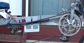
Well it works, so it's time to spill the beans on what I've been cobbling together. First the pictures :D
linear booster left side (Small).jpg
linear booster right side closeup (Small).JPG
Drive Unit (Small).jpg

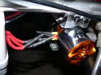
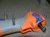
Motor: Cheap Chinese Motor (uses a standard RS-550 mounting bolt pattern)
ESC: Cheap Chinese ESC
Battery: 3.0Ah 12v NiCd battery left over from my first battlebot.
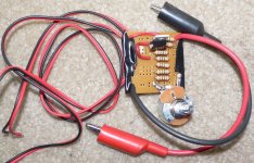
Throttle: AstroFlight servo tester
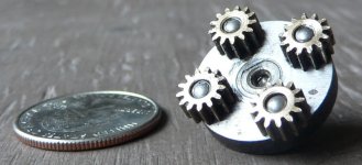
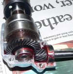
Gearbox: First Choice; What was actually in stock; What I'll be switching to
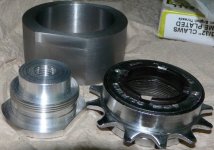
Freewheel: a cheap'o Shimono
Freewheel adaptor: Made my own but THIS Stanton-Inc adaptor would work just as well.
MVP: McM# 91458A21 Loctite 609 Retaining compound.

Well I've taken two test rides so far. The system does exactly what I want it to do, kill the two steep hills in my daily commute. The gearbox is rather noisy though it seems to be quieting down a bit. The cadence at maximum assist is about 45rpm, a bit too low for hill climbing. I'm switching to a 25:1 gearbox to up the cadence and improve efficiency by dropping a gearbox stage. I DO wish I could've used the BaneBots 42mm gearboxes, the extra pinions available for these boxes would've been a direct fit for the motor's 5mm shaft. As it is I had to turn down the motor's shaft to fit the pinion. (many inrunners and DC motors use a 3.2mm shaft size though) I've also found the weak spot in my system. Luckily the weak point is the glue joint connecting my freewheel adapter to the gearbox's output shaft, something easy to fix.

Oh yea, 2.45lb for 300-500 watts of assist into my chain :twisted:

Marty
 
Very nice! I had to look real closely to find the motor... :lol:

I assume the tape is for testing and not the final build. (No 40's 4U!)

:mrgreen:
 
Nice work Marty,

I have a general question regarding handling with that Linear layout and below the seat steering. Is it something you'd be comfortable with at higher speeds, say 35-40mph. Also, I've heard that weight shift is a major part of steering...would you be comfortable with someone behind you instead of the baskets, eg a wiggly 4 year old moving contrary to how you are shifting weight in turns?

John
 
John in CR said:
Nice work Marty,

I have a general question regarding handling with that Linear layout and below the seat steering. Is it something you'd be comfortable with at higher speeds, say 35-40mph. Also, I've heard that weight shift is a major part of steering...would you be comfortable with someone behind you instead of the baskets, eg a wiggly 4 year old moving contrary to how you are shifting weight in turns?

John

I am comfortable with the Linear at high speeds now. It was pretty hard to steer before I got rid of the backlash in the steering linkage. (4-ply zip-lock bag in the quick release ball joints) Fastest I've taken it is ~25mph, mainly because I'm lazy and don't feel like pushing air all the time. The handling IS subtly different though. With all the weight concentrated at the back, more steering input is required and the input needs to come earlier at low speeds. Also, it's usually best to lean into the seat as balancing is easier when the rider and bike move as a single unit. At high speeds the 'delay' goes away and it steers like a normal bike. In many ways heavily loading the rear rack of a conventional bicycle produces similar (but worse) handling.

A wiggly passenger? I have had it loaded down with two bags of groceries with my ~18lb backpack only loosely tied to the rack and seat stays. The wiggles weren't too bad if I stayed above walking speed. Below walking speeds I can just drop a leg for balance if needed. I'm also tempted to put a rack over the front tire. Loading that rack up would improve handling, but keep me from mounting a rain fairing. (the rain fairing is MORE tempting :) )

Marty
 
Thanks Marty,

I've heard recumbents steer differently, and I'm sure I can get used to it, but my next ebike has to be a kid hauler too. The look on my little Max's face when I leave alone when he's so used to always hopping in the car with Dad is something I have to eliminate without cranking up the smoker. I gotta capitalize on this last year before school starts, and I can't think of a better way than sharing the silence and fun of an ebike. If I make it good and zippy enough I may even volunteer to replace having to pay for a school bus for all 3 kids.

The simplicity of the Linear has a lot of appeal, so thanks for the feedback. I may give something similar a go, but with large tires and a lowered seat so I can get my lardass mass at or below axle level for added stability which would counter anything the kids might do to unbalance us. Let me see how the Worldbike layout I'm building works before I put myself down closer to bumper level. Most of my riding is mixing with traffic, so that's my one remaining concern where I see a big advantage going to a more upright bike.

John
 
Nice one, thats a far cry from my last linear...it weighed over 40KG with 84v of lead acid and an x'lyte motor on it :shock:

Great bikes....have fun with it!
 
Nice job..

It seems to me that adding a few more cells to your pack might be a cheaper and easier way to get your cadence up, with the added benefit of giving you more power.
 
file.php


I love these small motors... this is definitely progress. :)

2.43lbs... oh my that is just beautiful!
 
Regarding speed, I managed 55 mph with mine downhill on occasion, it flies as straight as a die thanks to long wheelbase. Slow speeds took a while to master though..
 
Right now it's about as loud as the wind noise at about 25mph. Most of that noise is from the cheap gearbox I'm using. (sounds a bit like a coffee grinder) Also, I opened my gear box up, and it shows signs of overloading. Cheap overloaded gears are always going to be noisy. The motor also makes some noise, but it's much more pleasant. The free wheel and my idler must also make some noise, but I haven't heard it yet :) Even under power, the bicycle chain makes almost no noise.

Now that I know I like this setup, It's easier to justify spending money. I've got some ideas on how to quiet this system down. The current plan is to switch to a bigger slower motor and try out helical gearing or belt drive.

Marty

Edit: Whoot! new toys in the mail. Just got the new gearbox and ESC input filter parts, I'll have this in a working configuration a much sooner than I thought. :D
 
Well, I put it back together this morning and took it out to test on my commute. Their's good news and bad news. The good news is my motor has LOTS of power and the gearbox efficiency was better. The bad news is my new transmission is missing about 20+ teeth after testing.

My motor is delta wound, so I'm going to try converting it to a star winding. Should drop the Kv to about 350 [rpm/volt] and cut the peak power output to 1/3 at 12volts. If that works I'll recycle parts to make a 12:1 gearbox and see if that survives for long at the reduced power.

Marty
 
This seems to be the only significant problem everyone who is trying the RC motor on ebikes is having. If somehow a really well built "Swiss Watch" type transmission could be built/found the RC motor will become the ideal solution.
 
safe said:
This seems to be the only significant problem everyone who is trying the RC motor on ebikes is having. If somehow a really well built "Swiss Watch" type transmission could be built/found the RC motor will become the ideal solution.

To be fair, I was pretty sure I'd lunch these gearboxes. The motor the gearbox is sold with has a stall current of only 45 amps, so about 100 watts is the most I'd expect the stock motor to produce. Almost anything will die when asked to operate at five to six times it's normal loading. The next larger size (which is out of stock :x ) is likely to have survived just fine.

Bha! the enamel on the magnet wire of my motor is NOT the solderable stuff. With almost 30 strands in each coil, this could take longer than I thought.

Marty
 
Well the my motor still works. It's now star wound with about a 360Kv. Fine sandpaper got rid of most of the insulation on the wires. A long dip in a micro-solderpot cleaned off what was left and made a nice joint. (Micro-solderpot, aka a hole drilled part way through an old soldering iron) Only had to re-bundle one set of strands. One of the strands was sorted into the wrong bundle shorting two of the phases.

I'll try to get it back together this weekend.

Linear Booster Power system (Small).jpg

On the left sticking out of the box is my key/precharge switch. Doesn't work, because the ~300 ohms of resistance it has is too much resistance when the controller beeps the motor. After that the controller refuses to start up. I'll put some smaller resistors in it to get it working. The black mass below the controller is my extra input filtering. It's ~2000uF of capacitors and a 30v TVS diode. Should keep the controller happy even with a 3-4 foot supply wire.

The last Picture is what I'm planning this to look like when it's done.

Marty
 

Attachments

  • deltastar.jpg
    deltastar.jpg
    9.4 KB · Views: 7,225
Well... It works. It can't be putting out much more than 100w now, but right into the chain 100w is a nice boost. Changing the motor to star winding reduced power enough that the gearbox survives. Also dropping to 12:1 reduced gear stress. With the 12:1 tranny and ~360Kv motor the pedals can spin faster than I'd like. A new problem did crop up when I made this switch. With the new gearing and motor wind the glue joint between the motor shaft and pinion broke. I guess my glue doesn't stick to brass that well. I soldered it up with some silver bearing solder I had left over. So far it's stayed stuck.

If I was going to do this again I'd just stick with the motor the gearbox comes with and get the right gear ratio. This 64:1 gearbox would be about right. Similarly I'd just use any old 30-40amp airplane ESC. I'd also get THIS Staton inc freewheel adaptor. To fit the freewheel adaptor I'd glue a McMaster# 6381K464 bronze bushing to the gearmotor's shaft with Loctite 609 or equivalent. Next I'd make dimples or groves in the outside of the bushing where the set screws from the freewheel adapter would go. Finally I'd attach the adapter with the set screws and a LOT of blue threadlocker.

I'm already thinking of version two. In preparation I'll be making an electrical model of my system so I can calculate my maximum currents with a given motor and loading. So that means making a Milli-Ohm meter. (just a calibrated one amp current source, the plans popped up here a few months ago) Current plan is to take a 200kv outrunner and do a Delta to Star switch for about 120Kv. Then run a single stage belt reduction of 7.5:1 with an overload clutch to drive the freewheel.

Marty

P.S. It's a LOT quieter now. I think all the noise earlier was my gearbox screaming in pain. :oops:
 

Attachments

  • P1110110.JPG
    P1110110.JPG
    43.3 KB · Views: 7,173
lawsonuw said:
P.S. It's a LOT quieter now. I think all the noise earlier was my gearbox screaming in pain.

Hi Marty,

Nice job!

How is it lubricated? You might want to contact John about this gearlube:
http://endless-sphere.com/forums/viewtopic.php?f=12&t=5325&p=93927#p93927

johnrobholmes said:
I also got some special gear lube that is supposed to make gears very quiet. The guy that blends it actually told me to get a dB meter and test the numbers!
 
The BaneBots gearmotors are lubricated with what looks like a cheap lithium grease. I've since upgraded to some "extreme pressure Molly-Lithium grease" I have laying around. The Molybdenum disulfide content of this grease improves efficiency and should make the gears last longer.

Gear noise isn't a big issue anymore, and listening to the gearbox gives me an idea of how much torque the motor is putting out.

Marty
 
About time I made some more updates.

First, my pre-charge switch now works. I lowered the resistance to about 30ohms and the controller beeps twice like it should.

Next I made a mili-ohm meter extension. (First picture below) It's all parts that can be found at the local Radio Shack. The 1.25 ohm 'resistor' is seven ten ohm resistors in parallel with a twenty-five ohm potentiometer in parallel. I run it off of the 3.3v output of the converted ATX power supply powering one of my chargers. The regulator drifts as it heats up, I really should add a head sink some time.

Third, I thought I'd post a picture of the gears I'm sending 100-150 watts through. It's the second picture below. They're puny and brass, yes that's a quarter to the left.

Fourth, I dropped some cash at the LBS and got a little more gear reduction for the motor. (see the last attached picture) Stuff should last a bit longer now.

I've also figured out how to install the set of Power Grips I bought a while ago. My feet are REALLY wide so the directions were no help. I've removed one of the screws holding the pedals together and screwed the outboard strap mount into it.

Last, everything seems to be holding up now. I can give the motor full throttle with about a 60rpm cadence (and my old gearing) and nothing breaks. I only use about three minutes of power on my whole commute. The motor should last a LONG time. 8)

Marty

P.S. The duct tape is here to stay on this version. :)
 

Attachments

  • P1110142.JPG
    P1110142.JPG
    108.2 KB · Views: 6,961
  • P1110144.JPG
    P1110144.JPG
    45.6 KB · Views: 7,054
  • P1110146.JPG
    P1110146.JPG
    63.6 KB · Views: 7,043
John got me thinking when he suggested using Dewalt drill motors and gearboxes for e-bikes. Normal drills are rather long and a challenge to find space for. So I started looking for angle drills. Harbor Freight has a few cheap ones, and they ever post .pdf manuals online with exploded parts views!

This and This looked interesting. What's the exploded drawing look like? ( Last two pages ) BINGO! we have a winner. I went an bought an example to dissect asap. (he local HF even had the orange one on sale 8) )

First picture shows the guts. Gearbox is 19.25:1 with metal gears and a round lip on the case near the output for easy mounting. 3/8 - 24 right hand tap for the chuck with a left handed locking screw. The long input shaft is 7mm at one end and 6mm at the other, shouldn't be too hard to turn it into a 5-6mm shaft and slip an RC outrunner onto it.

Second picture shows the series wound motor the drill came with. Spins at about 29,000rpm and rated for 3.2 amps at 120 volts ac. (a 382 watt input motor) The iron for the field is round with some flats. It would be really easy to make a replacement field with some neodymium magnets. This would dramatically lower the max rpm of the motor (hopefully to around 6000rpm) and let it work at 80-90 volts. The armature has about a 5.5 ohm resistance. Rewinding it for a lower voltage would be difficult as the armature was dipped in resin.

So, should I mod the existing motor, or should I graft a RC motor onto this bad boy?

Marty
 

Attachments

  • Harbor Freight Angle Drill.JPG
    421.6 KB · Views: 5,809
lawsonuw said:
...The long input shaft is 7mm at one end and 6mm at the other...

EDIT: whoops :oops: I guess it's not obvious WHICH end is 7mm and which is 6mm. (this stuff is also listed on the postit note in the first picture) The 7mm end is the one going into the gearbox. The 6mm end is ground into a double-D shape and uses a couple to connect to the motor. Note: This shaft is supported by only one ball bearing at the gearbox, the motor and coupling provides the other bearing for this shaft.

In between the ends the "shaft going to the gearbox" is like 6.5mm and NOT concentric with the ends. The small end with the double D for the motor is center drilled. (on center even from the looks of it) I'll check for a center drill on the end with the gear, and the shaft's hardness.

Marty
 
The input shaft of the HF drill's gearbox is un-hardened. It has a spiral bevel gear cut on it's end with another center drill. I also re-greased the gears while it was open. I'm currently leaning towards a RC system more. Motors are available with a 6mm shaft and 400-450kv which will work with the battery/controller I have now. (an 80 volt battery for the stock motor is just expensive any way you slice it)

In other news my current BaneBots transmission is getting quieter. The gearbox now makes about as much noise as the motor. (and it sounds less like a coffee grinder)

Likely next up on my list of mods is a wind/rain shield, and a current limiter. Progress will be slow as I'm rather busy this semester.

Marty
 
Well two new developments on this beast. First I figured out how to mount the angle drill! I'm replacing the top five case screws with 1.75 inch #8 sheet metal screws. An aluminum plate will be fabricated with hole positions matching the case, and inch long spacers are added between the case and mounting plate. (see my first picture) I've also drilled the mounting holes all the way through on the other case half. This will allow me to easily mark the locations of the mounting bolts on the future mounting plate.

Next I got busy in the machine shop. Made an adaptor to fit a 13T BMX freewheel onto the drill. 30mm M1 thread on the BMX, and a 3/8-24 UNF thread for the drill's chuck mounting. (the thread I actually made is a 26tpi and a little under size, darn lathe predates the use of metric threads in the USA :p ) Also made a shiny new field iron for the drill's motor. Even if I don't use the drill's stock motor I've got to see if this works like I'm expecting. (Magnet the field iron was designed for will use 10 )

Last Picture is what the guts of this drill's gear box look like. The gears aren't all that large and the output bearing setup is a questionable for my use, but for less than $30 I can live with it. While it was open I replaced the unknown red grease with my leftover super gear grease.

Marty
 

Attachments

  • How to mount the HF drill.JPG
    How to mount the HF drill.JPG
    48.5 KB · Views: 6,832
  • Freewheel adaptor and new Field iron.JPG
    Freewheel adaptor and new Field iron.JPG
    52.1 KB · Views: 6,717
  • My next (gearbox) victom.JPG
    My next (gearbox) victom.JPG
    83.2 KB · Views: 6,716
Back
Top