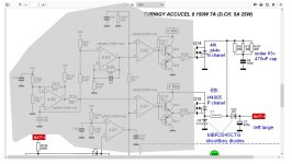
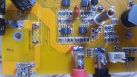
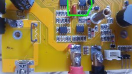
whatever
100 kW
- Joined
- Jun 3, 2010
- Messages
- 1,297
so I have to test the irf4905 P-chanel mosfet I took out before puting it back, which means the method using lightglobe and battery has to be changed for P-chanel fet, pics below show the changes
( also will put in new thread on mosfet testing as is handy method for testing fets, very quick also if you have little circuit or breadboard setup).
Using 12v battery with 12v lightglobe no resistor needed in this method:
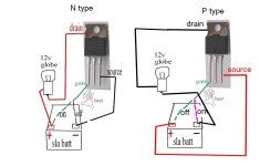
using led to test mosfets requires resistor 1k in size in series with led globe, I will test with 9v battery also, would make for compact test unit
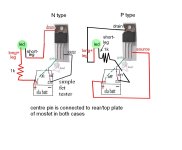
Although I posted this method back in 2010 ( idea from Warwick Smith from Numurkah secondary school...that guy is absolutely brilliant, not sure what he is doing these days on this forum for 12v testing link to that here:
https://endless-sphere.com/forums/viewtopic.php?t=19585
I went searching for info on P-chanel fets, and came across a really nice video that shows breadboard version for N and P chanel. Its an amazingly simple setup. Also in his comments section someone suggests if using a wire instead of your hand to turn on/off the fet ( via the gate leg) that a resistor should be used on that wire also. Some of the comments are worth a read on this vid:
[youtube]https://www.youtube.com/watch?v=p-PouEtYbns[/youtube]
( also will put in new thread on mosfet testing as is handy method for testing fets, very quick also if you have little circuit or breadboard setup).
Using 12v battery with 12v lightglobe no resistor needed in this method:

using led to test mosfets requires resistor 1k in size in series with led globe, I will test with 9v battery also, would make for compact test unit

Although I posted this method back in 2010 ( idea from Warwick Smith from Numurkah secondary school...that guy is absolutely brilliant, not sure what he is doing these days on this forum for 12v testing link to that here:
https://endless-sphere.com/forums/viewtopic.php?t=19585
I went searching for info on P-chanel fets, and came across a really nice video that shows breadboard version for N and P chanel. Its an amazingly simple setup. Also in his comments section someone suggests if using a wire instead of your hand to turn on/off the fet ( via the gate leg) that a resistor should be used on that wire also. Some of the comments are worth a read on this vid:
[youtube]https://www.youtube.com/watch?v=p-PouEtYbns[/youtube]


