I recieved my set of resistors by the mail today and made some preliminary testings. They are rated for 5% precision and 50W power... For me, it's perfect as the lowest value resistor (0,5 Ohm) shows less than 7A when placed on each of my cells which drops about 0.15 V (so about 7Watts..). Worst cell I tested (a totally dead on arrival cell (extremely rare in Makita Packs from my experience), salvaged at 0.03V, experimentally soldered on its positive teminal and charged to 4.20V.... With a horrible 1923 mAh instead of 2100.....) dropped 0.31 V, so it's still safe with that 50W resistor (about 14-15 Watts).
I took one of my good Sony VTC4 (date code on it is 2015 april) and tested it :
RESISTOR ............... Volts ............ Amps
0.5 Ohm ................3.818 V ............ 6.67 A
1.0 Ohms ...............3.876 V............. 3.68 A
2.0 Ohms ...............3.915 V..............1,91 A
2.2 Ohms................3.920 V..............1.76 A
4.0 Ohms ...............3.938 V..............0.98 A
None (float)............3.964 V..............0 A (measured before the 0.5 Ohm resistor measure... the external resistance is that of the multimeter which is astronomically high... meaning that the current is neglectible)
NB : Amp measures are taken all on the same scale (my meter is NOT an auto-scaling multimeter, so I dont have the problem of a mutimeter that changes from calibration shunt to calibration shunt... causing some break in the graph slope)
I have to be really fast with the 0.5 Ohm resistor, otherwise I end up discharging the cell to much. Hence, this is the first measure I do in order to avoid biasing the next measure. If I'd do the 0.5 Ohm measure at a moment other than being the first measure, it would overestimate the cell resistor by 20-25% more. The 1.0 Ohm can also be a problem if I'm not fast enough to take measure. 2, 2.2 and 4 Ohms are no problem as the voltage goes back to identical float voltage after pulling.
I then plotted the data on a graph where Amps are on abciss (x) and Volts are on ordinate

... I get a slop in the form of y = mx + b that translates into
V = -r I + E
where V is voltage
r is the internal resistance of cell
E = electromotrice force (which corresponds to float voltage with no current, here it is around 3.96V)
(for more teaching on this mathematical relationship/equation, see this vid : https://www.youtube.com/watch?v=Uz4X8i9ubeA)
Here is the graph (x axis is current in A while y axis it potential in volts) :
View attachment 2
so the slope of -0.0209 corresponds to -r .
That means r = 0.0209 Ohms or 20.9 milliOhms.
So in conclusion, the DC internal resistance of my april 2015 Sony UR18650 VTC4 cell is 20.9 milliOhms at 23°C and 80-85% State of Charge (3.96V). Not too shabby :wink: This is totally consistant with previous results obtained here with some new VTC4 : https://endless-sphere.com/forums/viewtopic.php?f=14&t=73701#p1112249 (see point 4. the 6th graphic shown). Cells from DoctorBass are very affordable and seem to be as good as new, judging from my capacity testings and this DCIR preliminary testing !... (I know doctorbass stores them in a cool place around 10-15°C and not fully charged)...
With ideal conections, my future battery builds will have quite low resistance. I have 290 scavenged cells. Will test them all and make 3 battery pack (14S) that I'll use with a BBSHD mid drive I have (max 30A controller).
Pack #1 (14S10P) will be for long rides and to have fun with some WOT action and speed runs

!.... So in theory, 23.8 milliOhms which means 0.7V sag under full load at 30Amps.
Pack #2 (14S6P) will be for some mid lenght trips... Not so heavy at 3.8 kg. Will be 49 milliOhms, so 1.5V sag under full load at 30 Amps (I plan to use it at less that 30 amps). 8)
Pack #3 (14S4P) will be for short commutes (12-14 km roundtrip) in town... To be used with gentle throttle or PAS. Goal on this pack is range... not to flug it WOT all the time (probably cruising at 5-7 amp with 15-20Amps peaks at accelerations). With theoretical DCIR of 73.5 milliohm, that small 2.8 kg pack will sag by 2.2V at full 30 amp load (but i dont want to push it that hard)

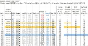
Here's my breakdown :
View attachment 1
...Tired of being an eBike amateur... So I'm starting to use my brain more and do calculations

Matador


