Alright, so all the parts have arrived in the mail, or well, most of them did a couple weeks ago, but I haven't bothered to update this thread yet.
I've decided against that BMS, and I think I'll probably get this one instead: http://www.foundingpower.com/chanpinzhanshi/houbeidianyuanchengtao/73.html
I like that it has this pretty looking LCD display:
It's pretty much perfect for my 16s nissan leaf battery pack. It handles exactly 16 cells, has four thermal sensors, I have four batteries. Pretty much an ideal fit.
It'll have to wait though, I'm broke after buying all this stuff. I just hope the cells stay fairly balanced while being bulk charged for a month. I do have a friend's Hyperion EOS0606i, which I can use to charge/balance up to 6 cells at a time, but seeing as it's only 50W and this battery pack is 2kWH, that's really not ideal.
So anyway, I got the batteries a couple weeks ago and set about taking them apart and wiring them in series. Most people seem to take them out of their cans entirely, then I guess they wrap them somehow to compress the pack? I'd rather not deal with that, so I decided to leave as much of the cans intact as possible, that way I can bolt them together for compression, like they were originally designed for.
Here's an album of that process: http://imgur.com/a/ULQfj
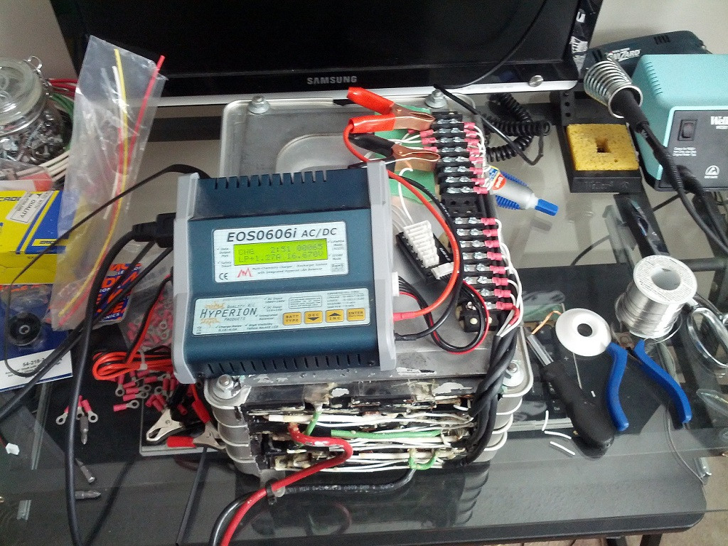
Then, while I waited for my bulk charger to arrive, I balanced the cells using a friend of mine's 50W balance charger:
(The signs are for my roommates, who are very special people. They have an uncanny knack for accidentally destroying my stuff through sheer ignorance.)
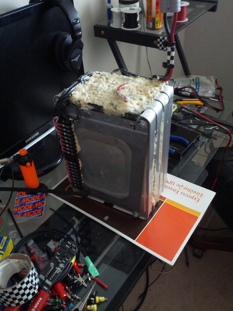
Next, once all the cells were charged and balanced, I wired everything up like so:
I'm happy to say I never shorted anything out at any point, though I was terrified I would at some point.
Next step was to disassemble my bike and hook everything up. It was a sunny day, perfect to work outside.
That's what the inside of a Motorino XPD looks like. There's surprisingly no photos of this online. If anyone has trouble taking one apart I'm happy to answer any questions.
So this is the stock rat's nest of wires. I mostly took this for reference in case I missed something, but it proved to be less than helpful. I didn't get any photos of the "After", but I was able to clean up the wiring a bit with a liberal application of zip ties.
The unplugged connectors are for the charging port, the alarm, and a random spare 12v line for no reason.
Here we have our patient, ready for the operation. Also shown are the alarm and wimpy stock dc-dc converter.
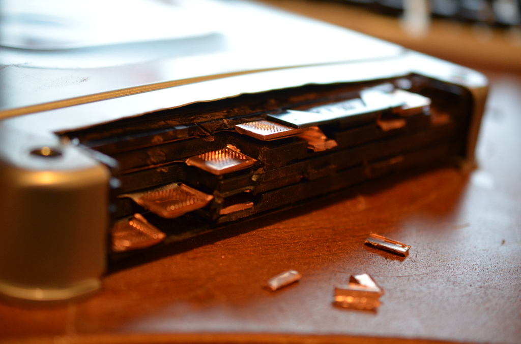
These 63v caps will need to go. Unfortunately it's a snug fit, the case was obviously designed around these caps. My 100v replacements are taller, so I'll need to attach wires to their leads:
While I was in there I also put some bigass solder blobs on the shunts. I'm not really sure how much to use, so I covered up like a third of them. Dunno what I'm doing here, and I have no clamp-on ammeter to test. No idea what my stock amperage was either. The controller says 40A, but I'm certain my motor wasn't pulling that, as it's rated for 500W.
¯\(°_o)/¯
Just a shot of my workspace. It was really nice to work outside. I should solder in the back yard more often.
The heatsink the FETs are attached to was covered with a thin smear of that really cheap white silicone thermal compound, which I proceeded to get all over everything. I wiped that all off and replaced it with Arctic Silver 5, which ought to help cool a bit.