Upload Your Circuit Schematics & Requests Here...

Mr. Electric used one of the TNC controllers up to 60v, but that model lacked a current limiter and he had to add one. Often times the only difference in the circuit between various voltage controllers is where the low battery cutout is set.

I have partial schematics of several brushed controllers. The basic layout is the same on most of them.

I'm sure if you got just about any of them, they could be modified. It would be best if it had a current limit in the ballpark of what your motors will handle. You also would need to be sure it wasn't one that is potted with epoxy.

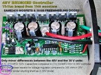
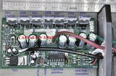
Whatever you get, you just take it apart an read the numbers off the FETs and diodes to determine their ratings. The main capacitor(s) will be marked with a voltage rating too. The low voltage regulator may be a bit trickier, but there are several ways around that. Either a pre-regulator or run the regulator input off a tap on the batteries.
 
Not a schematic, but at least a photo of one of the 36V TNC brushed (Yi-Yun brand) controllers with the major components identified:

COMPONENT SIDE:
 

Attachments

  • ControllerTopIDsm.jpg
    ControllerTopIDsm.jpg
    90.5 KB · Views: 3,492
One thing I was wondering about the FETs in the controller I posted above.... I can't find any real information on the part numbers on the internet; The only thing I was able to find was on some blog that indicated the NEC3435s were 60V units.

You would think that the NECs at least would have some documentation. And the alternating ones, the HBRs.... Are they even fets? The only 20100 s I can find are Schottkys, and that seems to be a pretty common number between various Mfgs.

I have run the 36V controller 'on the bench'... (I don't have a bike ready yet for real world testing) at 44V for hours, with the throttle at max and no load on the motor. And I also got the load to surge a few times up to 18 Amps with no problems to the controller.

I have another one from TNC, the Yi-Yun 48V one on the way... Should be here Tuesday or Wednesday. I'll post photos of it like the ones above with major components ID for comparison.

Two modifications I want to make on these brushed controllers, and I hope some of you can lead me in the right direction:

I want to make the low voltage cutoff adjustable; Down to ~ 26V on the 36V controller, instead of the 31V that the factory sets. I assume that by replacing a fixed resistor with the proper value of pot will do that, but I don't know WHICH resistor to replace.

And, if possible, I want to modify the 48V controller to be able to handle 130V at at least 10A (20A would be better, but I can live with 10) .

Would it be safe to assume that replacing the FETs and the freewheel diode and the caps with higher voltage ones, and maybe adding some heatsinking and/or active cooling would be all that is necessary?
 
I want to make the low voltage cutoff adjustable; Down to ~ 26V on the 36V controller, instead of the 31V that the factory sets. I assume that by replacing a fixed resistor with the proper value of pot will do that, but I don't know WHICH resistor to replace.

Oh, now that I re-read Fechter's last comment, changing the LVC may not be as easy as I'd hoped. :?

Or am I confusing the problem with increasing the LVC cutoff for battery pack safety on increasing the voltage being the problem, not lowering it.

To tell the truth, I'd be willing to do without a LVC at completely.... With a Watt's Up or Cycle Analyst, or just a regular old volt meter and a pair of eyes, I can figure out when it is time to start pedaling harder or start walking and pushing.
 
I especially like their lockable bike luggage trunks for $15.


Don't get those. They're just a really cheap piece of plastic. $15 is too much.

I think you should try running the 48v controller at 72v+. That controller seems to have no "bells and whistles" I bet there's no maximum for current. I"m going to run mine at 56v to start, but I'm sure I'll upgrade to 64v soon after.

 
If you're running a higher voltage, the LVC won't do anything until your batteries are really dead. I run without one. Just use the CA or a voltmeter to watch your batteries.

The 20100's are schottkey diodes. Those are the freewheel diodes.

The LM7815 is the voltage regulator. It is fed by a resistor. To run a higher voltage, you would need to change that resistor, since the input of the 7815 is rated for 35v.

The 3435's are rated for 60v, 80A, and have 14mohm on resistance. Attached is the datasheet.
 

Attachments

  • 2SK3435 datasheet.pdf
    79.1 KB · Views: 395
  • YK42 topside.jpg
    YK42 topside.jpg
    90.1 KB · Views: 3,913
Oh, Cool! Where did you find that data sheet? I must have spent two hours on Google and the NEC site and couldn't find it.

Oh, never mind. Now that YOU provided it already, I was able to find it on the NEC website in about 90 seconds DOH! (I wish they had a Homer Simpson emoticon here, I really need one now.)

And very glad to know that the 20100s are the freewheeling diodes. My understanding of this controller is now one order of magnitude better, thanks to you.

I did know that the 7815 was a voltage regulator, although I thought it was a 15V one..... Oh, wait. INPUT 35V (DOH! again..... I know JUST enough about electronics to look like a fool.)

Well, when the 48V controller comes in, I'll post photos, and ask for detailed advice on modifications.

Thanks again.
 
That controller doesn't look too bad. If you changed the FETs, caps and that one resistor for the voltage regulator, you could bump the voltage up to near 100v. I'm not sure about the freewheel diodes, they might be OK for 72v.
It would be harder to make it a wide input range, since the regulator resistor must be chosen for the desired voltage and won't tolerate too much variation.

With higher rated FETs and diodes, you could mess with the current shunt if you wanted more amps. Likewise you could lower the current limit by removing part of it.
 
RLT said:
To tell the truth, I'd be willing to do without a LVC completely.... With a Watt's Up or Cycle Analyst, or just a regular old volt meter and a pair of eyes, I can figure out when it is time to start pedaling harder or start walking and pushing.

Don't do with the LVC. You'll eventually damage your batteries.

Pack voltage cutoff isn't good enough. One cell drops too low and you'll damage it -- even with pack voltage within normal range.


Richard
 
rf said:
RLT said:
To tell the truth, I'd be willing to do without a LVC completely.... With a Watt's Up or Cycle Analyst, or just a regular old volt meter and a pair of eyes, I can figure out when it is time to start pedaling harder or start walking and pushing.

Don't do with the LVC. You'll eventually damage your batteries.

Pack voltage cutoff isn't good enough. One cell drops too low and you'll damage it -- even with pack voltage within normal range.


Richard

Please Do Not do WITHOUT an LVC.

Brain in neutral this morning ...


Richard
 
On that LVC circuit. Was poking about mouser and found a few quad optos that might be preferrable to the cny17.

http://www.avagotech.com/search/results.jsp?src=&siteCriteria=ACPL847


Richard
 
I'll admit I'm pretty dumb about motor controllers, But I don't believe that the LVC protects you from an single unbalanced cell or two, any more than watching your voltmeter and knowing when to turn the power off.

You would need something like the balance connectors and monitoring circuitry that the RC guys use on their high end batteries and chargers for every cell to be monitored... or a protection circuit like these:
http://www.batteryspace.com/index.asp?PageAction=VIEWCATS&Category=711
to achieve what you are talking about.

In general, I think that the LVC is just an attempt to idiot proof the systems for 'normal' people who just want to ride and not have to pay attention to the boring details of their machines, not for people who frequent these forums and have the basic knowledge and passion to get the most out of their machines.

Just like the custom LED lights using Lithium Ion batteries I have built over the last several years: The ones I build for sale or to give to "regular people" have protection circuits built in. The ones I keep for myself or that go to people that I KNOW are aware of the problems of unbalanced cells, under and over charging , etc. , I usually leave the protection circuits out unless they ask for protection.

I'd rather have the option of over-draining a cell or a whole pack in an 'emergency' than to maybe be stranded somewhere, either in the dark in the case of lights, or on the road or trail on a EV.

JMHO.
 
48V Brushed motor Controller: Yi-Yun Brand, from TNC Scooters:

I have to admit, I'm a little surprised. There are really only three differences that I can see between the 36V Yi-Yun brand brushed motor controller (pics posted on previous page of this thread) and the 48 V one.

The MOSFETS (3435) and the 20100 Schottky freewheel diodes are the same!
I guess that isn't a real big surprise since the fets are rated at 60V 80A, and the Schottkys are rated to 100V.... But still, for 70% higher price, there ought to be more powerful semiconductors, don't you think ? ;)

The only differences that I can see is that:

A: instead of the seven 330MFD 63V capacitors, there are four 470MFD @ 100V units.

B: The power resistor to the 7815 voltage regulator is 1200 Ohms as opposed to the 390* ohm one on the 36V controller.

C: There is a small short of solder between the shunts on the 36V, none on the 48V.

That's it, as far as I can tell. Almost not worth posting a picture, but here it is anyway:

*: The resistor on the 36V MAY be 290 ohms. I can't tell for certain whether the first stripe is red or orange from the photos, and I don't particularly want to go find the 36V controller now and open it up to be sure. But my best guess is that it is orange.
 

Attachments

  • 48V-l.jpg
    48V-l.jpg
    66 KB · Views: 3,786
So, If a guy wanted to modify one of these Yi-Yun controllers to handle 130V at at least 20 Amps;

?? How close do you need to be to the original values of RDS(on)1 = 14 mΩ MAX. (VGS = 10 V, ID = 40 A) ??

The closest I can find in that range is a 16m ohm 150V 79A Fairchild 2532.
http://www.fairchildsemi.com/ds/FD/FDP2532.pdf

I'd prefer to use 200V fets since I'm planning on running right around 130V, but the closest RDS that I can find in 200v is 40 m ohm at 200V is a IRFP260NPBF @ 49A:
http://www.irf.com/product-info/datasheets/data/irfp260n.pdf

(There are a few other 200 V at 60-80 m ohm, and a bunch at .even higher)

I don't expect to exceed 20A peak {(well maybe 22A on the steepest hills), and that is if I upgrade to the next motor; the one I plan to use for now is only rated at 8A.}

Then upgrade the freewheeling diodes to 20200s:
http://www.onsemi.com/pub/Collateral/MBRF20200CT-D.PDF

Don't know what to do about the capacitors; Was planning to use seven 330MFD 160V, but since the 48 V controller uses four 470MFD 100V ones, I'm a little confused as to what is the smartest way to handle that.

And what for the power resistor? Something like a 3 watt 3.6K ohm?
 
Yes, funny how the pricing has little to do with what's inside.

For the FETs, you want to get the lowest on resistance you can find.
an IRFB4321PBF or FDP2532 would be my choice. You can run these right up to the maximum voltage rating.

The 20200 freewheel diodes should be OK.

The capacitors just need to be rated for a higher voltage than you're going to run, and as much capacitance as you can physically fit in the space. More is better. The physical size of the caps will be the determining factor.

It would be good to take a voltage measurement across the regulator resistor when the thing was running to get an idea for the current it's taking. You want the input leg of the 7815 to be around 20-30v over the expected range of battery voltage. Once you know the right resistance, you can calculate the power. To run at 130v, that resistor is going to be throwing off a LOT of heat. It will need to be quite large.

Another approach would be to replace the resistor with a transistor/zener pre-regulator. This would give you a much wider input voltage range. The transistor would be dissipating all the heat, and it could be bolted to the case somehow. This is how the Crystalye controllers do it.
 
i have had occasion to repair several Crystalyte motors now. mostly people rip out the hall sensor wires somehow or other. for this reason i built a simple tester that just plugs into the motor and using a 9V battey for power lets me test the Hall Sensors for output. it is a simple circuit but useful.
 
rkosiorek said:
i have had occasion to repair several Crystalyte motors now. mostly people rip out the hall sensor wires somehow or other. for this reason i built a simple tester that just plugs into the motor and using a 9V battey for power lets me test the Hall Sensors for output. it is a simple circuit but useful.

A useful circuit for testing!
Seems that you could add an LED to monitor the hall supply.
 
The7 said:
rkosiorek said:
i have had occasion to repair several Crystalyte motors now. mostly people rip out the hall sensor wires somehow or other. for this reason i built a simple tester that just plugs into the motor and using a 9V battey for power lets me test the Hall Sensors for output. it is a simple circuit but useful.

A useful circuit for testing!
Seems that you could add an LED to monitor the hall supply.

Yes, that's a great idea.

This should be built into the controller! That would add like 25 cents to the cost.
 
fechter said:
The7 said:
rkosiorek said:
i have had occasion to repair several Crystalyte motors now. mostly people rip out the hall sensor wires somehow or other. for this reason i built a simple tester that just plugs into the motor and using a 9V battey for power lets me test the Hall Sensors for output. it is a simple circuit but useful.

A useful circuit for testing!
Seems that you could add an LED to monitor the hall supply.

Yes, that's a great idea.

This should be built into the controller! That would add like 25 cents to the cost.

i don't really see a purpose to add it to the controller. it is only usefull for diagnostics. at most speeds all of the LED's would change so rapidly that they would just appear to be on all of the time.

the LEDs change pattern in 6 states. these are:
1. amber
2. amber+green
3. green
4. green+blue
5. blue
6. blue+amber

i also prefer to measure the hall voltage directly from the controller. it should be 13V or so.

recently i repaired a couple of motors where the hall sensors were damaged by over-voltage from the controller. it was more than 18V. i just replaced the zener and the pass transistor in the controllers to drop this back down to the 13V
 
I have seen how an SCR with a resistor tied between the Gate and the Cathode will reduce the sensitivity of the SCR to prevent it from latching "on" from a trivial or spurious input at the gate. In a simple circuit simulator I played around with a PNP / NPN transistor pair (a functional equivalent of an SCR) and was able to get the "SCR" to turn off at different holding currents based on changing the value of a resistor between Gate and Cathode. In my tinkering, I found a 5ohm resistor raised the holding current of the "SCR" to ~130mA. Once the current dropped below ~130mA, the "SCR" turned off. This seemed to be in the realistic range for terminating a charging cycle. This got me to thinking...

Is this realistic? I was using an online java circuit simulator, so it is admittedly not very sophisticated.

Is there a way to calculate the required gate-to-cathode resistance to establish a certain holding current? What properties of the SCR do you need to know to calculate it?

How reliable would this be for acting as a low current shutoff? ie. would the circuit be extremely sensitive to variations in temperature, component variance (5% or 1% resistors) etc.

What will the voltage drop through the SCR be?
 
OneEye said:
...In my tinkering, I found a 5ohm resistor raised the holding current of the "SCR" to ~130mA. Once the current dropped below ~130mA, the "SCR" turned off. This seemed to be in the realistic range for terminating a charging cycle. This got me to thinking...

...What will the voltage drop through the SCR be?

That's an interesting idea. I've never tried it, but it might work. I think the voltage drop in the SCR is around 0.7v.
 
I've been digging to try to find more information on using a resistor to set the holding current (Ih) of an SCR. I've had little luck.

This patent application from 1980 ( http://www.freepatentsonline.com/4223281.html ) mentions a gate-to-cathode resistor is used to set Ih. This resistor tie is also shown in their 'prior art' figure (attached). The SCR is the transistor pair enclosed in a dashed box labeled 14. The gate-to-cathode resistor is R2. The patent obviously covers a different innovation.

I still see the potential to use a simple SCR and resistor as the low-current shutoff mechanism in a charging circuit. SCR's seem to come in a great variety of allowable voltages and amps, so it would be trivial to find an inexpensive SCR to fit a charging circuit for anything from 3.6v per cell to a 100V+ series some of you seem to love so much.

Unfortunately I don't have the answers about what information and equations you would use to determine the required resistance based on your desired holding current. I also don't know how sensitive the SCR would be to non-ideal conditions (different temperatures, resistor tolerance, etc). I'm assuming all you EE types have all of this info at hand and are just holding your tounges in a grand conspiracy against us CE types who don't know what a flip-flop does or how you can possibly multiply in binary using only NAND gates. :lol:

-Mike
 

Attachments

  • SCR Gate to Cathode.gif
    SCR Gate to Cathode.gif
    14.8 KB · Views: 3,731
I had a big SCR lying around and hooked it up for a test.
Once latchted, it would unlatch at about 120ma with the gate open.
I tried several resistors from gate to cathode, but non of them seemed to change the dropout current much. Even with the gate shorted to the cathode, it was still about 120ma.

I does make a nice way to automatically disconnect a bulk charger once the current gets down to 120ma. I think the SCR is rated for 600v.

Perhaps a smaller SCR or one with a sensitive gate might behave differently.
 

Attachments

  • Big SCR.jpg
    Big SCR.jpg
    258.1 KB · Views: 2,701
Back
Top