Vectrix 102 cell NiMH Battery Analysis

Mr. Mik

1 kW
Joined
Sep 3, 2008
Messages
390
Hi,

I'm new on this forum. :D

I have been reading the recent thread on NiMH Thermal Balancing and found it most interesting. There seems to be a good knowledge base about NiMH issues on ES.

My Vectrix is out of warranty and I call it the Vectux.

I am planning to dismantle the NiMH battery pack in order to determine if any of the 102 cells are damaged or under-performing. I am also considering to install a BMS, Cycle Analyst or other monitoring system whilst the battery is in pieces.

It will be a big job, taking up at least a full week, maybe a month.

I have an IMAX B5 Balance Charger to play with and a West Mountain CBA2 battery analyzer in the mail.

I have previously removed the batteries in order to enable motor controller repairs, but have not yet taken the individual cells apart.

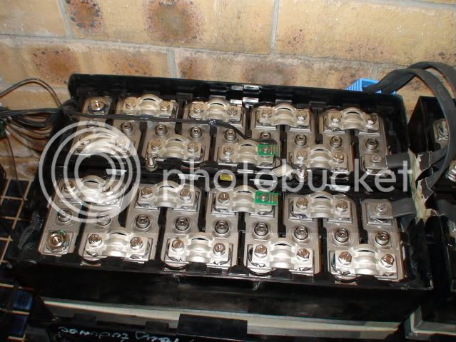
DSC03915-2-1.jpg


I need ideas about how to plan this, in order to minimize downtime, and maximize knowledge gain.

There will undoubtedly be more questions once the cells are separated from each other, but I need a clearly laid out testing and recharging plan to follow once I begin to dismantle the cells, or the spontaneous discharge rate will make individual cell results more difficult to compare to each other.

I hope to get away with about 1hr per cell for internal resistance and capacity testing, and then 6 hrs to recharge a set of 6 cells at a time.

Any suggestions how to tackle this?
 
I dont know anything about scooters, but have been using NiMh for quite a while. What capacity and voltage for the system and how many cells? I count 54 but i cant tell if there is a second layer. It sounds like the BMS keeps charge percent between the high and low, sort of like the Prius.
otherDoc
 
docnjoj said:
I dont know anything about scooters, but have been using NiMh for quite a while. What capacity and voltage for the system and how many cells? I count 54 but i cant tell if there is a second layer. It sounds like the BMS keeps charge percent between the high and low, sort of like the Prius.
otherDoc
They say 125V, 30Ahr, 3.7kWhr.

The number of cells is 102.

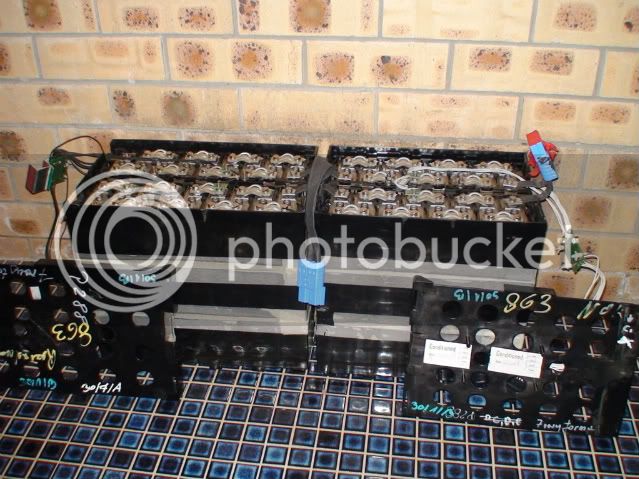
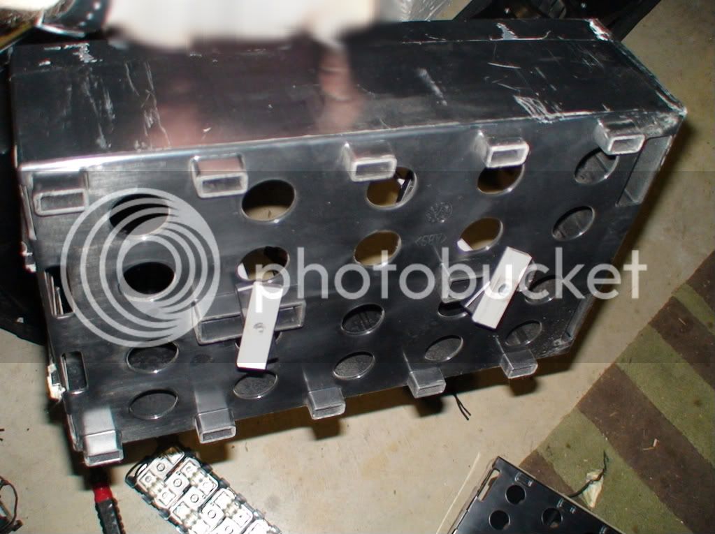
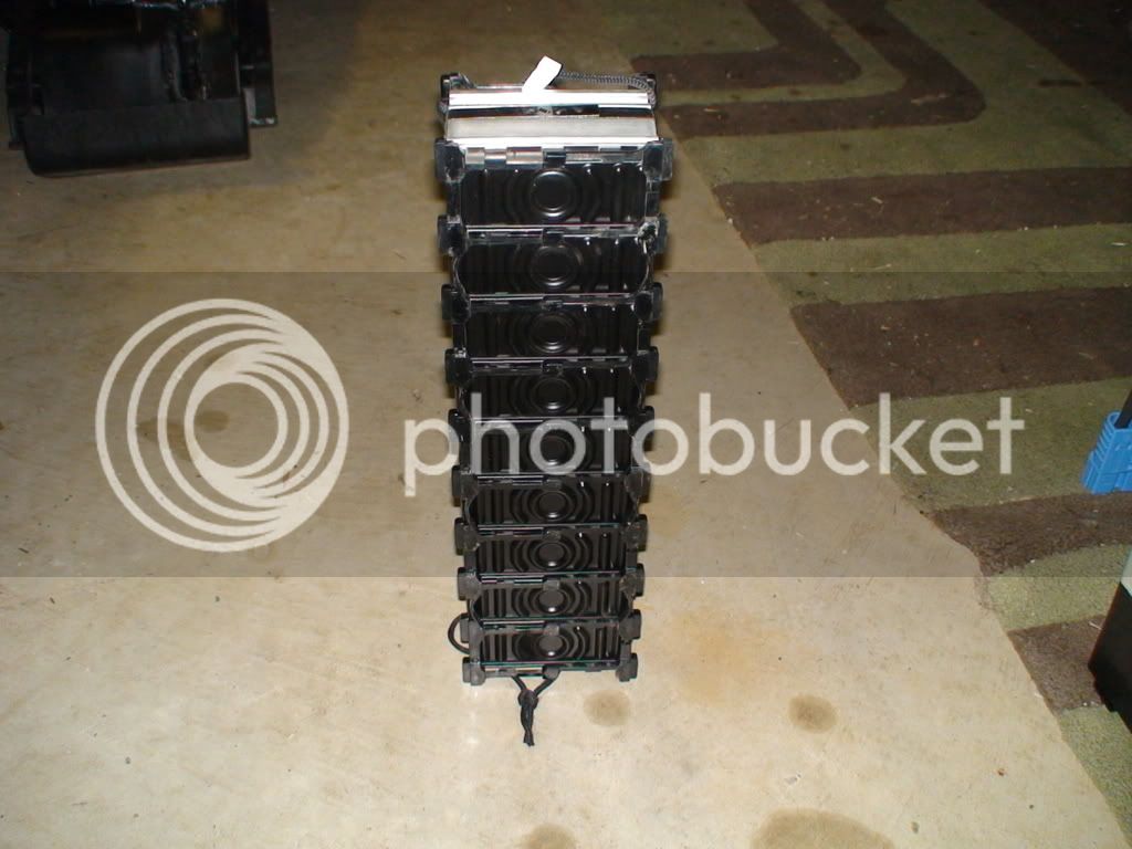
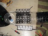
They are arranged three layers deep in two separate aggregates:

DSC03918-1.jpg


The larger one on the left is the rear battery in the scooter and weighs 47kg. It has two strings of 27 cells in it.
The smaller one weighs 42kg and has a single string of 48cells in it.


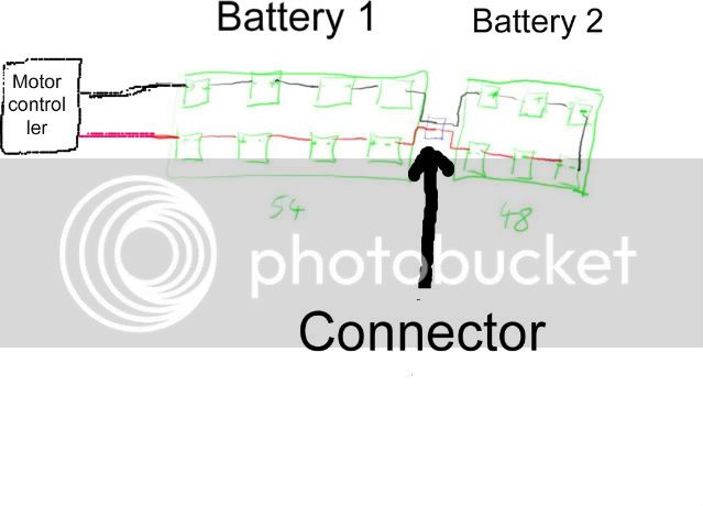
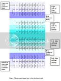
Here is a schematic to show the principle - the cell numbers are different:

Batteryschematicb-1.jpg


This design is making it possible to disconnect the batteries without potentially getting exposed to the full voltage.
 
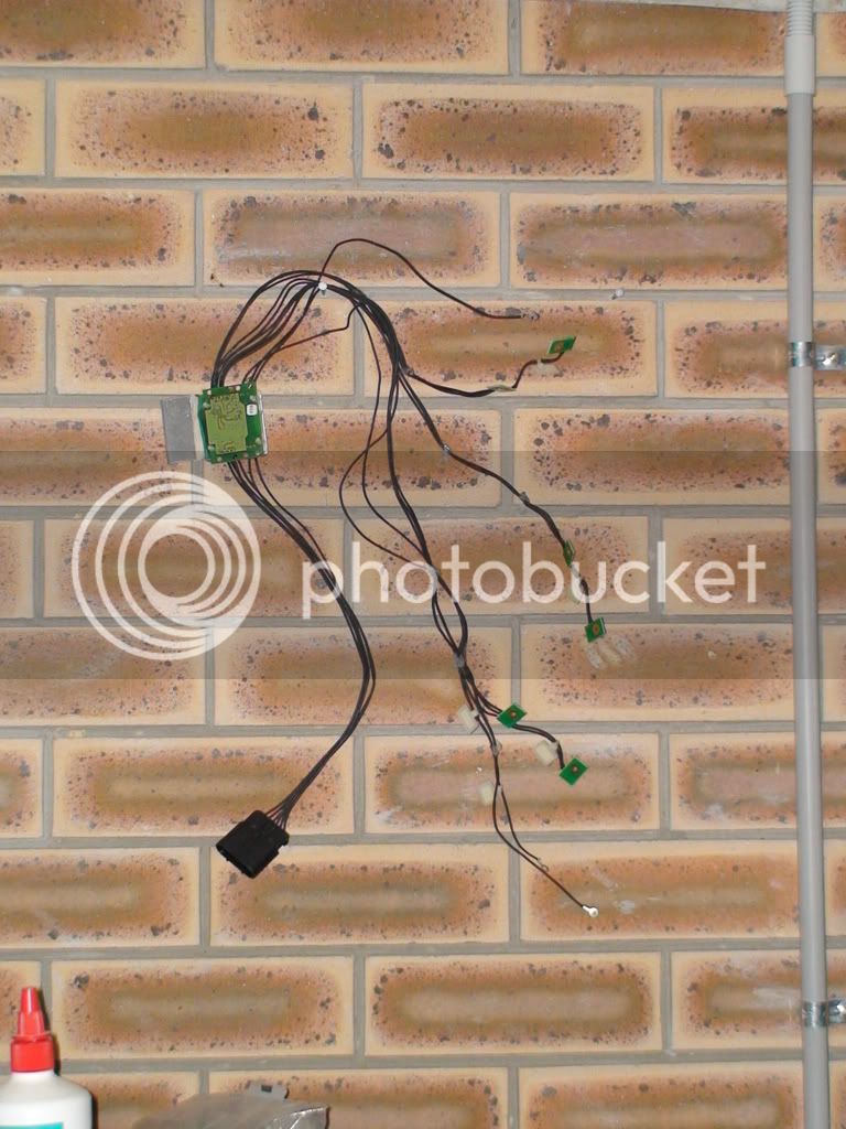
The multiple small black and white cables coming out of the packs are the connections to the 12 temperature sensors spread throughout the two packs.

I am planning to take the cover off the batteries soon and to remove one or a few cells in order to prepare for the big job.
Then replace them so the scooter runs until I am ready to work on it daily for at least a week.

The aims:

1) Determine torque settings to be used in the re-assembly of the pack. Let me know if you have any idea how to do this, please! (I have torque wrenches)

2) Prepare a connector that easily and securely attaches to the cells for the 204 measurements and 17 recharges.
This needs to include a good, fast thermal connection for the temp sensor which is on the way together with the West Mountain CBA2 battery analyzer.
I am considering to do an initial resistance test on each cell as described in the CBA2 owners manual:
Charge the pack, set the CBA, for example, to 11 A; assuming the battery is safe at that level. Run the test
for 30 seconds and record the voltage at the end of this test. Run a test again at perhaps 1 amp for another
30 seconds and record the voltage again. If the battery has .5 volts less at 11 A than it does at 1 A use
Ohms law: R=E/I. R being resistance in Ohms, E is voltage in volts and I current in amperes. The internal
resistance of the pack, in this example, would be: R = .5/10 or .05 ohms. Note that we used the difference
in current between the two tests of 10 A.
and then a capacity test on each cell.

3) allow inspection of an individual cell.

4) start marking/numbering the cells, at least the top layer.

5) assess if and how fast temperature measurements of the cells can be obtained in order to assess if they receive different amounts of fan forced cooling air flow. This will have to be a fast and well planned operation to enable comparison of all cell temperatures before they spontaneously equalize. IR thermometers might or might not work reliably on the reflective metal surface of the cells. I hope the plastic cover around the cells can be removed quickly to allow access to one surface of each cell so that I can take temp readings with an IR thermometer. Maybe I'll record sound whilst calling out the battery number and corresponding temperature reading, then transcribe it later and cross reference it with the internal resistance values.
I might have to paint pats of the cells to enable IR temp measurements.

6) do a test run of resistance and capacity measurement and recharging procedure using the IMAX B5 Balance Charger.
 
Thank you, Olaf.

I hope you are right about there likely not being any temperature differences.

Temperature differences might occur due to varying internal resistance and high current draw or over-charging.

The temperature could also differ between cells because less of the heat is removed from some areas of the pack due to differences in the air flow pattern.

During riding air enters through inlets under the front fairing, during recharging two fans continuously suck lots of air in through the same inlets and pump it out above the rear wheel. Sometimes these fans also start to run during or after riding, or when the scooter has just finished charging and the batteries are very warm.

I believe that I need to dis-assemble the pack because if I did discharge one cell at a time, running the capacity test whilst it is still connected to the other cells, that would surely cause some trouble, maybe destroy the pack???

It might also be impossible to get to the two lower layers of cells with alligator clips.

And I would like to check that all connections are firm, especially the ones between the three layers of cells.

Today I have jerry-rigged a hoist to lift the batteries out more easily and set up a space to do the testing when all is ready to go.

So far the plan is to ride the Vectux until 1/2 empty, then remove seat, battery cover etc and place the scooter in the right spot under the hoist, then jack it up into a stable position on a concrete block. Then I'll loosely place the cover back on, just enough to keep the air-flow characteristics unchanged from normal, but removable in seconds.
Then I'll do a full recharge, followed immediately by lifting off the cover, disconnection of the blue connector between the three strings of cells in the batteries, removal of the pos and neg battery cables and temp sensor cables, attachment of the hoist and lifting out of the batteries.
Then immediately measure individual cell temperatures.
...
A slow test run will be done first to test and practice it all, the plan might change....I'll keep your suggestions in mind!
 
Welcome to the forum !

Interesting pack, nicely built from the looks of it, any model/brand/etc info on the cells themselves ?

A few different ways to do this, but if it was me and i wanted to know the health of the pack without getting too fancy... i'd rig up a stationary load ( like a big honking resistor or a wack of lightbulbs )

Check the voltage of each cell , note..( yes. all 102. gulp.. i have done similar things with a big string of D cell nimh 8ah , 72v, time consuming, but fun if you are that geeky !! :p )

Discharging/charging the whole pack in one shot will speed things up considerably and you don't have to seperate the cells to do it. Also a good way to assess the charge termination of your charger !!
 
Thanks, I'll consider that, too!

No writing on the visible parts of the cells; Parker-Hannifin made, I believe.
EDIT 2010-09-07: Cells are made by Gold Peak.

More detailed photos of the pack can be viewed in this previous post on V.
 
I got a reply to an email enquiry from BattEQ makers Smartsparkenery today: Unfortunately no NiMH BattEQ is available yet.

They are prioritizing the work on the SolarBridge and do not know when/if a NiMH EQ will be made, although the Switched Capacitor System is theoretically suited to all battery chemistries.

Does anyone reading this have the experience to take an educated guess if a Switched Capacitor System could be home-made and how difficult it would be?


At a guesstimated cost of AU$6000.- for a battery replacement for the Vectux it would be cost neutral to build a BMS that increases lifespan of the pack by 30% even if it costs AU$2000.- (Excluding my labor, that is paid for by the learning experience!)

If it is made from durable components then it might be used again in the next pack, or even in a pack with a different chemistry.

Or what other approaches to make a NiMH BMS could be taken?

Maybe it is not even remotely useful to install an equalizer into a Vectrix NiMH pack.

I hope we will be able to clarify this in the next few weeks.

The West Mountain CBA2 battery analyzer should be here tomorrow and things will be a lot less theoretical from then on!

I'll probably test it on a few innocent NiMH AAA's to get my bearings before diving into the Vectux pack...
 
Welcome!

Yes, that is an ambitious project. Looking at what Honda and Toyota do with their hybrid packs, I would suggest testing blocks of cells, like 6 or 7, whatever is convenient. If one block tests significantly differently, then it may warrant testing at a single cell level.

I designed a switched capacitor balancer, but using available switched capacitor IC's the current was very low, like 100ma. It would also take a crapload of them for that pack.

Other battery managment schemes for large Nimh packs usually involve measuring the voltage at every 6 - 8 cells and using a microprocessor to limit the charge and discharge.

A modified version of my LiFePO4 BMS circuit could provide a similar function. I would not recommend monitoring every cell, but again groups of cells.

One problem is charging Nimh is different than lithium. Detecting end of charge is trickier but they make chips designed to do this. Simple temperature controlled charging might work too if there were enough temperature sensors.
 
If you are interested in a Data logger that is capable of measure up to three temperatures, volts, ampere and so on, you may like this one:

http://www.hobbycity.com/hobbycity/store/uh_viewItem.asp?idProduct=4575&Product_Name=MicroPower_V3_E-Logger

This way you can compare your batteries blockwise (up to 70V) while you drive and download the logged Data to your PC and compare it.

-Olaf
 
Thank you for your replies. Most helpful.

There is some trouble with my Photobucket account, nothing seems to work right at the moment.
All the old links have disappeared, too. Hope that gets sorted.
So, no pictures for now. :cry:

I did consider monitoring blocks of cells with a PackTracker before, and data logging might be very interesting indeed.

I'll have time to research these options once the capacity testing is under way. All 102+ hrs of it...

It took longer than expected to solder connectors onto the CBA2 and the Imax B5 charger, but now it's all ready to roll.

Test runs on a very mixed bunch of AA, AAA and "D" NiMH cells continue to teach me about the glitches etc. which I might encounter during testing of the 102 cells. Very nice toys, the CBA2 and the charger.

I decided to go with the flow instead of trying to design the optimal setup for the test. I just have to accept that the Vectux will be off the road for several weeks. It has been running well for several thousand kilometers now - good to enter into "preventative maintenance" territory for once!

The rear battery is now dismantled and the front battery will be next.

I did fully charge the batteries with the on board charger before taking it apart, but as the Real World has it, it behaved strangely during the last recharge, just to muck things up!
Instead of displaying EC, and counting down for the last hour of charging, it showed CP and continued to count up, then stopped after about an hour. But the current draw was as it would have been in EC mode.


The battery is "relatively" full and should be about as balanced as the Vectrix BMS can achieve.

I hope that starting with a full pack will allow more accurate comparison of the individual cell's capacity.

Because it will take weeks to complete testing, I might wait a few days before starting the capacity testing, as spontaneous self-discharge is highest early on. Apparently up to 10% on day one. So if I wait at least 24hrs after the last charge, then the differences between cells might be less due by self discharge. And I have more time to get ready...

------------------------------------------------------------------------------------------------------------------------------------------

The interesting results so far:

1) Torque for the inter-battery connection bolts is 10Nm. Using my torque wrench in reverse, I could loosen most of the screws with 8-9Nm torque. Re-tightening them at 10Nm caused the same result, so the setting I will use is 10Nm.

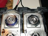
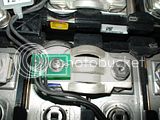
2) The battery recall was indeed necessary - it appears to me that the bolts holding the "inter-level-connectors" have been torqued to 5Nm (the lowest one was only 3Nm) instead of 10Nm. These bolts are the same size as all the others, but have different letters and numbers on the top.
My guess is that the batteries were assembled into packs of 8 and 9 cells at the battery factory, using correct torque settings; and then the assembly into complete packs of 102 cells was buggered up somewhere else by using 5Nm instead of 10Nm to tighten the bolts holding the battery temp sensors and the connectors between the three layers of cells.
None of the connectors in the rear battery had actually rattled loose - guess that says something about the tolerance level built into that part of the scooter.

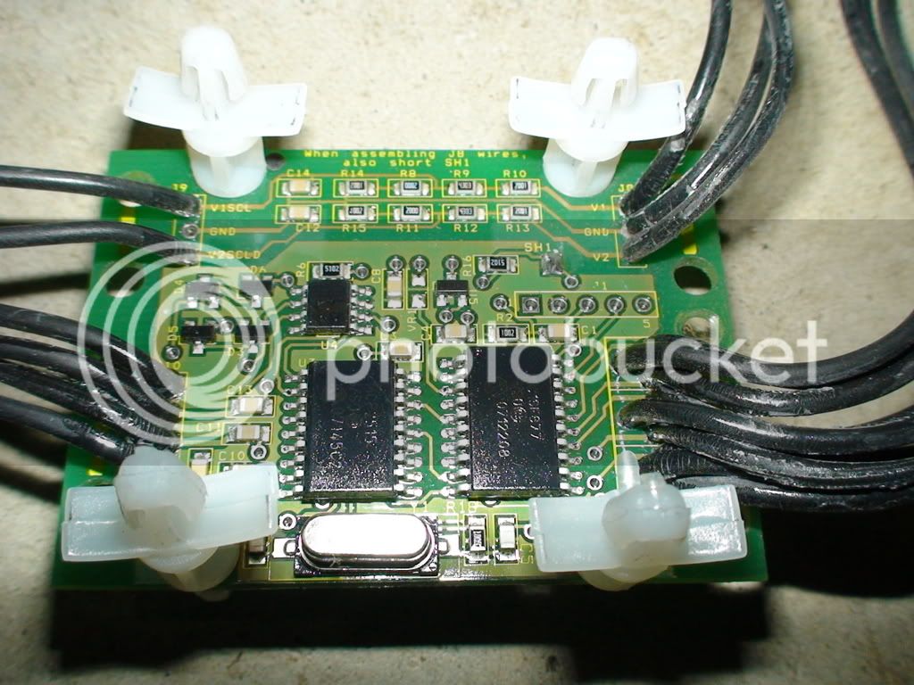
3) There are 2 voltage sensors (and a ground connection) in addition to the 6 temp sensors in the rear battery,
I am expecting more voltage sensors in the front battery, will find out soon.

More when Photobucket works again...
 
Photobucket still seems to be going through some turmoil....

Now the old linked photos are back, but my "Albums" have disappeared....

So yesterdays pics will have to do for now:

The interesting results so far:

1) Torque for the inter-battery connection bolts is 10Nm. Using my torque wrench in reverse, I could loosen most of the screws with 8-9Nm torque. Re-tightening them at 10Nm caused the same result, so the setting I will use is 10Nm.

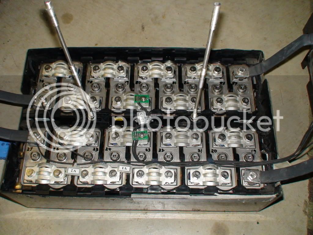
2) The battery recall was indeed necessary - it appears to me that the bolts holding the "inter-level-connectors"
DSC05007.jpg

have been torqued to 5Nm (the lowest one was only 3Nm) instead of 10Nm. These bolts are the same size as all the others, but have different letters and numbers on the top.
I'll make an educated guess that the batteries were assembled into packs of 8 and 9 cells at the battery factory, using correct torque settings; and then the assembly into complete packs of 102 cells was buggered up somewhere else by using 5Nm instead of 10Nm to tighten the bolts holding the battery temp sensors and the connectors between the three layers of cells.
None of the connectors in the rear battery had actually rattled loose - guess that says something about the tolerance level built into that part of the scooter. But tightened to the correct torque of 10Nm will make tham much safer!

3) There are 2 voltage sensors
(and a ground connection) in addition to the 6 temp sensors in the rear battery,
I was expecting more voltage sensors in the front battery, but there are none.

Added 2008-09-18: Sorry, but I just learned that the conventional way to number batteries in series is to start with Nr1 at the negative end of the series. I took a punt without researching it and got it wrong!


DSC05084.jpg


Some more pictures:

DSC05108.jpg


DSC05025.jpg


DSC05117.jpg


DSC05125.jpg
 
What kind of cells did they use?
otherDoc
 
docnjoj said:
What kind of cells did they use?
otherDoc
I am not sure, but believe they are a custom cell for the Vectrix.


Added 2008-09-18: Sorry, but I just learned that the conventional way to number batteries in series is to start with Nr1 at the negative end of the series. I took a punt without researching it and got it wrong!


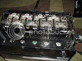
This photo shows the entire 102 cells and the way that they are connected in series when they are inside the scooter.

The thin black and the thin red cable are added in to show where the shorter leads of the blue connector would be connected to.

 
Here are the first capacity test results:
Added later: THESE ARE ALL WRONG DUE TO CABLE AND CONNECTOR RESISTANCE! SEE POSTS BELOW!


Added 2008-09-18: Sorry, but I just learned that the conventional way to number batteries in series is to start with Nr 1 at the negative end of the series. I took a punt without researching it and got it wrong!


The testing started 25hrs after the last recharge, so about 10% capacity might have been lost to spontaneous self discharge.

I set the voltage cutoff at 1.1V. This is quite high and causes a lower capacity to be found than if, say, 0.9V was used as the cutoff voltage.
The reason for this is that the Vectrix electronics shut down power delivery to the motor at a battery string voltage of 108V.
108V / 102 cells = 1.0588V/cell.

The CBA 2 software allows 0.1 increments in cutoff voltage, so I chose 1.1V. Maybe I could have typed into the field and used 1.06V but I thought of it too late. Now I want to continue with the same setting for all cells to make the results more easily comparable.

The discharge current was set as 20A. Although the CBA2 can apparently test a single NiMH cell at up to 25A (to a cutoff level of 0.9V) it gives a warning message at anything over 20A.
So I kept it at 20A.

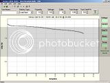
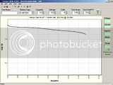
This is the discharge curve for the first cell (I numbered them starting from the cell at the POS end of the string.):


10.56Ah capacity under these specific conditions.

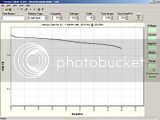
The next screenshot shows the overlay of the discharge curves of cells 1 to 5:


Nicely balanced by the looks of it.
 
Here are part of the txt file the CBA2 allows to export after a test.

They show the capacity for the first 20 cells tested.

I wonder if there is a systematic error of sorts which causes the gradual decline in capacity.

Added later: YOU BET!!! THESE ARE ALL WRONG DUE TO CABLE AND CONNECTOR RESISTANCE! SEE BELOW!

It might also be due to spontaneous self discharge.

Any ideas about this, anyone?

Here is the data:


Added 2008-09-18: Sorry, but I just learned that the conventional way to number batteries in series is to start with Nr1 at the negative end of the series. I took a punt without researching it and got it wrong!


West Mountain Radio - CBA
Test Report: Vectux Cell Nr 1

Description: 1 NiMH cell, 30.0 Ah @ 20.00A
Started At: 09/14/08 18:08:22 E. Australia Standard Time
Discharge Rate: 20.00 A
Starting Voltage: 1.20 V
Ending Voltage: 1.10 V
Total Time (hh:mm:ss): 0:31:41
Tested Capacity: 10.56 Ah


West Mountain Radio - CBA
Test Report: Vectux Cell Nr 2 error 0.9V cutoff

Description: 1 NiMH cell, 30.0 Ah @ 20.00A
Started At: 09/14/08 18:58:33 E. Australia Standard Time
Discharge Rate: 20.00 A
Starting Voltage: 1.20 V
Ending Voltage: 1.18 V
Total Time (hh:mm:ss): 0:00:30


West Mountain Radio - CBA
Test Report: Vectux Cell Nr 2 repeat at 1.1V cutoff

Description: 1 NiMH cell, 30.0 Ah @ 20.00A
Started At: 09/14/08 19:03:31 E. Australia Standard Time
Discharge Rate: 20.00 A
Starting Voltage: 1.19 V
Ending Voltage: 1.10 V
Total Time (hh:mm:ss): 0:30:50
Tested Capacity: 10.28 Ah


West Mountain Radio - CBA
Test Report: Vectux Cell Nr 3

Description: 1 NiMH cell, 30.0 Ah @ 20.00A
Started At: 09/14/08 19:45:23 E. Australia Standard Time
Discharge Rate: 20.00 A
Starting Voltage: 1.20 V
Ending Voltage: 1.10 V
Total Time (hh:mm:ss): 0:31:30
Tested Capacity: 10.50 Ah


West Mountain Radio - CBA
Test Report: Vectux Cell Nr 4

Description: 1 NiMH cell, 30.0 Ah @ 20.00A
Started At: 09/14/08 20:25:17 E. Australia Standard Time
Discharge Rate: 20.00 A
Starting Voltage: 1.20 V
Ending Voltage: 1.10 V
Total Time (hh:mm:ss): 0:31:10
Tested Capacity: 10.39 Ah


West Mountain Radio - CBA
Test Report: Vectux Cell Nr 5

Description: 1 NiMH cell, 30.0 Ah @ 20.00A
Started At: 09/14/08 21:02:47 E. Australia Standard Time
Discharge Rate: 20.00 A
Starting Voltage: 1.20 V
Ending Voltage: 1.10 V
Total Time (hh:mm:ss): 0:30:44
Tested Capacity: 10.24 Ah


West Mountain Radio - CBA
Test Report: Vectux Cell Nr 5

Description: 1 NiMH cell, 30.0 Ah @ 20.00A
Started At: 09/14/08 21:02:47 E. Australia Standard Time
Discharge Rate: 20.00 A
Starting Voltage: 1.20 V
Ending Voltage: 1.10 V
Total Time (hh:mm:ss): 0:30:44
Tested Capacity: 10.24 Ah


West Mountain Radio - CBA
Test Report: Vectux Cell Nr 7

Description: 1 NiMH cell, 30.0 Ah @ 20.00A
Started At: 09/14/08 22:28:11 E. Australia Standard Time
Discharge Rate: 20.00 A
Starting Voltage: 1.20 V
Ending Voltage: 1.10 V
Total Time (hh:mm:ss): 0:31:09
Tested Capacity: 10.38 Ah


West Mountain Radio - CBA
Test Report: Vectux Cell Nr 8

Description: 1 NiMH cell, 30.0 Ah @ 20.00A
Started At: 09/14/08 23:07:02 E. Australia Standard Time
Discharge Rate: 20.00 A
Starting Voltage: 1.20 V
Ending Voltage: 1.10 V
Total Time (hh:mm:ss): 0:30:41
Tested Capacity: 10.23 Ah


West Mountain Radio - CBA
Test Report: Vectux Cell Nr 9

Description: 1 NiMH cell, 30.0 Ah @ 20.00A
Started At: 09/14/08 23:42:17 E. Australia Standard Time
Discharge Rate: 20.00 A
Starting Voltage: 1.19 V
Ending Voltage: 1.10 V
Total Time (hh:mm:ss): 0:29:48
Tested Capacity: 9.93 Ah


West Mountain Radio - CBA
Test Report: Vectux Cell Nr 10

Description: 1 NiMH cell, 30.0 Ah @ 20.00A
Started At: 09/15/08 00:33:30 E. Australia Standard Time
Discharge Rate: 20.00 A
Starting Voltage: 1.20 V
Ending Voltage: 1.10 V
Total Time (hh:mm:ss): 0:29:05
Tested Capacity: 9.69 Ah


West Mountain Radio - CBA
Test Report: Vectux Cell Nr 11

Description: 1 NiMH cell, 30.0 Ah @ 20.00A
Started At: 09/15/08 05:38:54 E. Australia Standard Time
Discharge Rate: 20.00 A
Starting Voltage: 1.20 V
Ending Voltage: 1.10 V
Total Time (hh:mm:ss): 0:28:44
Tested Capacity: 9.58 Ah


West Mountain Radio - CBA
Test Report: Vectux Cell Nr 12

Description: 1 NiMH cell, 30.0 Ah @ 20.00A
Started At: 09/15/08 06:16:41 E. Australia Standard Time
Discharge Rate: 20.00 A
Starting Voltage: 1.19 V
Ending Voltage: 1.10 V
Total Time (hh:mm:ss): 0:28:50
Tested Capacity: 9.61 Ah


West Mountain Radio - CBA
Test Report: Vectux Cell Nr 13

Description: 1 NiMH cell, 30.0 Ah @ 20.00A
Started At: 09/15/08 06:52:03 E. Australia Standard Time
Discharge Rate: 20.00 A
Starting Voltage: 1.19 V
Ending Voltage: 1.10 V
Total Time (hh:mm:ss): 0:28:42
Tested Capacity: 9.57 Ah


West Mountain Radio - CBA
Test Report: Vectux Cell Nr 14

Description: 1 NiMH cell, 30.0 Ah @ 20.00A
Started At: 09/15/08 07:41:09 E. Australia Standard Time
Discharge Rate: 20.00 A
Starting Voltage: 1.19 V
Ending Voltage: 1.10 V
Total Time (hh:mm:ss): 0:28:32
Tested Capacity: 9.51 Ah


West Mountain Radio - CBA
Test Report: Vectux Cell Nr 15

Description: 1 NiMH cell, 30.0 Ah @ 20.00A
Started At: 09/15/08 08:14:02 E. Australia Standard Time
Discharge Rate: 20.00 A
Starting Voltage: 1.19 V
Ending Voltage: 1.10 V
Total Time (hh:mm:ss): 0:28:43
Tested Capacity: 9.57 Ah


West Mountain Radio - CBA
Test Report: Vectux Cell Nr 16

Description: 1 NiMH cell, 30.0 Ah @ 20.00A
Started At: 09/15/08 09:25:46 E. Australia Standard Time
Discharge Rate: 20.00 A
Starting Voltage: 1.19 V
Ending Voltage: 1.10 V
Total Time (hh:mm:ss): 0:29:32
Tested Capacity: 9.84 Ah


West Mountain Radio - CBA
Test Report: Vectux Cell Nr 17

Description: 1 NiMH cell, 30.0 Ah @ 20.00A
Started At: 09/15/08 09:59:08 E. Australia Standard Time
Discharge Rate: 20.00 A
Starting Voltage: 1.19 V
Ending Voltage: 1.10 V
Total Time (hh:mm:ss): 0:28:48
Tested Capacity: 9.60 Ah


West Mountain Radio - CBA
Test Report: Vectux Cell Nr 18

Description: 1 NiMH cell, 30.0 Ah @ 20.00A
Started At: 09/15/08 10:34:12 E. Australia Standard Time
Discharge Rate: 20.00 A
Starting Voltage: 1.19 V
Ending Voltage: 1.10 V
Total Time (hh:mm:ss): 0:29:08
Tested Capacity: 9.71 Ah


West Mountain Radio - CBA
Test Report: Vectux Cell Nr 19

Description: 1 NiMH cell, 30.0 Ah @ 20.00A
Started At: 09/15/08 11:10:15 E. Australia Standard Time
Discharge Rate: 20.00 A
Starting Voltage: 1.19 V
Ending Voltage: 1.10 V
Total Time (hh:mm:ss): 0:28:24
Tested Capacity: 9.47 Ah


West Mountain Radio - CBA
Test Report: Vectux Cell Nr 20

Description: 1 NiMH cell, 30.0 Ah @ 20.00A
Started At: 09/15/08 11:49:03 E. Australia Standard Time
Discharge Rate: 20.00 A
Starting Voltage: 1.19 V
Ending Voltage: 1.10 V
Total Time (hh:mm:ss): 0:28:51
Tested Capacity: 9.62 Ah

End of data......................................................................................................................

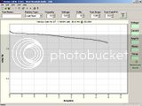
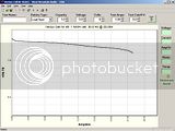
This next screenshot shows Cell 1 and cell 20 curves:


Here are some more questions I need some help with, if you please could answer:

Could I just add on a 30sec discharge test at 10A at the end of the capacity tests to calculate internal resistance?
The curve seems to be still quite flat at that stage so I think this might be feasible.
Or would different voltages be better for this purpose, maybe a 10A and a 1A run of 30s each?
I am not always at the computer when the test finishes by reaching the 1.1V cutoff, so it might be better to run two tests with varying voltages rather than "tagging on" only one more test, because there would be a varying time interval between cutoff level being reached and the next test.
Any suggestions how to best do this? Which voltages and for how long?

It would save a lot of time if I could do the resistance testing when the individual cell is already connected. It takes time to screw the cables to the cells for the measurements:


And how - if adviseable at all - should I best recharge the cells with the IMAX B5 charger?
 
I think the cables and paticularly the connector are introducing too much resistance.

The cable temp is 27C and the connector 33C in 24C ambient temperature.

Pulling the connector apart and then re-connecting it prior to testing cells 22 23 caused higher capacity results again:
10.01Ah and 10.21Ah.

I guess I'll solder much thicker cable straight to the CBA2 and to two of the inter-cell connectors to get rid of this problem.
 
I have soldered thicker cables straight to the CBA2:


The results appear massively improved so far:
West Mountain Radio - CBA
Test Report: Vectux Cell Nr 25

Description: 1 NiMH cell, 30.0 Ah @ 20.00A
Started At: 09/15/08 21:38:47 E. Australia Standard Time
Discharge Rate: 20.00 A
Starting Voltage: 1.32 V
Ending Voltage: 1.10 V
Total Time (hh:mm:ss): 1:17:07
Tested Capacity: 25.71 Ah

Taking into account the 55hrs since the last charge the result of 25.71Ah probably very close to true this time.

I'll just have to figure out how to best complete the discharges of the 24 cells measured with the old setup.

I need to point out that I did solder a different connector to the West Mountain CBA2 battery analyzer before doing any tests.

The local electronics shop people told me that the Andersons connector that was originally on it is rated to 25A, and the cconnector I replaced it with is supposedly rated to 70A. ( I was initially planning 30A or 40A discharge rates)

So, maybe the CBA2 would have been fine for the job if I had not done anything to it.....

But I believe the thicker cables are an improvement.

Anyways, a valuable lesson learned. Amazing how an increase in resistance by 11% can cause the Ah rating (AKA Range) to drop to less than half!

I was initially worried about my soldering when the cables coming out of the CBA2 measured a temp of 33°C during the Cell 25 measurement; but it turns out (by running the CBA2 without the red bottom part for Cell 26 and using an IR thermometer) that the soldering is fine, the cables just act as a heat sink.

Is it normal for the 25A fuse in the CBA2 to heat up to 68°C at 20A???
 
As I have mentioned in the above posts: I was not aware of the conventional numbering system for cells in a battery string and unfortunately started to count upwards from the positive end of the string, the opposite of how it should be.

It is too much effort to change all the file names, and the text displayed in the .bt files that the CBA2 software produces cannot easily be changed at all.

So for now I'll stick with the erroneous numbering system.
It's easy enough to calculate 103 - "incorrect cell number" = correct cell number if you need to know the correct number in the string.
So I'll call the cells "103-x", with "x " being the number I have written on the cells.

Here is the data from Block "13-4," containing cells 103-28 to 103-35.

(Since I soldered thicker cables without connectors to the CBA2 I am getting consistent results.)

===============================================================================================
West Mountain Radio - CBA
Test Report: Vectux Cell Nr 103-28

Description: 1 NiMH cell, 30.0 Ah @ 20.00A
Started At: 09/16/08 13:43:25 E. Australia Standard Time
Discharge Rate: 20.00 A
Starting Voltage: 1.31 V
Ending Voltage: 1.10 V
Total Time (hh:mm:ss): 1:12:57
Tested Capacity: 24.32 Ah


Test Report: Vectux Cell Nr 103-29

Description: 1 NiMH cell, 30.0 Ah @ 20.00A
Started At: 09/16/08 15:02:58 E. Australia Standard Time
Discharge Rate: 20.00 A
Starting Voltage: 1.31 V
Ending Voltage: 1.10 V
Total Time (hh:mm:ss): 1:11:33
Tested Capacity: 23.85 Ah


Test Report: Vectux Cell Nr 103-30

Description: 1 NiMH cell, 30.0 Ah @ 20.00A
Started At: 09/16/08 16:38:40 E. Australia Standard Time
Discharge Rate: 20.00 A
Starting Voltage: 1.31 V
Ending Voltage: 1.10 V
Total Time (hh:mm:ss): 1:13:13
Tested Capacity: 24.41 Ah


Test Report: Vectux Cell Nr 103-31

Description: 1 NiMH cell, 30.0 Ah @ 20.00A
Started At: 09/16/08 18:25:44 E. Australia Standard Time
Discharge Rate: 20.00 A
Starting Voltage: 1.31 V
Ending Voltage: 1.10 V
Total Time (hh:mm:ss): 1:11:51
Tested Capacity: 23.95 Ah


Test Report: Vectux Cell Nr 103-32

Description: 1 NiMH cell, 30.0 Ah @ 20.00A
Started At: 09/16/08 19:43:34 E. Australia Standard Time
Discharge Rate: 20.00 A
Starting Voltage: 1.31 V
Ending Voltage: 1.09 V
Total Time (hh:mm:ss): 1:13:20


Test Report: Vectux Cell Nr 103-33

Description: 1 NiMH cell, 30.0 Ah @ 20.00A
Started At: 09/16/08 21:01:50 E. Australia Standard Time
Discharge Rate: 20.00 A
Starting Voltage: 1.31 V
Ending Voltage: 1.10 V
Total Time (hh:mm:ss): 1:12:36
Tested Capacity: 24.20 Ah


Test Report: Vectux Cell Nr 103-34

Description: 1 NiMH cell, 30.0 Ah @ 20.00A
Started At: 09/16/08 22:23:52 E. Australia Standard Time
Discharge Rate: 20.00 A
Starting Voltage: 1.31 V
Ending Voltage: 1.10 V
Manually cut off at 1.1V : Tested Capacity: 24.47 Ah
Total Time (hh:mm:ss): 1:10:54
Tested Capacity: 23.63 Ah


Test Report: Vectux Cell Nr 103-35

Description: 1 NiMH cell, 30.0 Ah @ 20.00A
Started At: 09/17/08 04:23:56 E. Australia Standard Time
Discharge Rate: 20.00 A
Starting Voltage: 1.31 V
Ending Voltage: 1.10 V
Total Time (hh:mm:ss): 1:10:10
Tested Capacity: 23.39 Ah

=================================================================================================

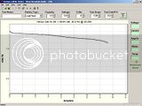
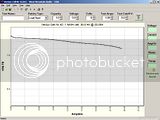
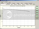
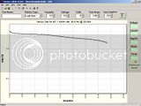
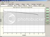
Here are the screen shots (click to enlarge):


And here the overlay of the 8 cells - this block 13-4 seems to have relatively well matched capacities and/or balanced cells:


Unfortunately this is not the case with all the 12 blocks. I'll post more later on.
 
 
Here are the screenshots from Block 13-5:


And here is the overlay:


About 1.5Ah difference in capacity between the highest and the lowest capacity cell.

But block 13-5 still looks kind of acceptable to me....
 
But Block 13-6 contains an abnormal cell:
(This is where the graph-overlay function of the CBA2 shines!)


Here are the individual graphs:


Over 9Ah reduced capacity in cell 103-48...this one will will get a closer look when the first run of tests is done.


Looks pretty good to me also! I wish my 10 ah cells were in that good shape! Thats only 5% difference at 20 amps! those are really good quality cells!
otherDoc
 
Back
Top