Victpower A123 20AH 48volt battery pack

dnmun said:
now you posted up that it does charge and you can discharge so what is the deal? if the BMS works why do they have to replace it and why did you file a paypal complaint?
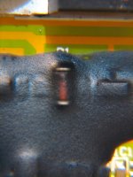
Did you watch the video? A simple touch will stop the charge.
Some have said cold solder joint @FET's, you say sense wires.
Does your pack intermittently charge if the BMS is bumped?
Yes, I'm totally wet behind the ears but I do not think that intermittent charging if the BMS is bumped with a purchased pack an OK deal.
But I'm no expert by any measure when it comes to BMS systems and how they work.
I have listened to your advice and allowed ~six hours on the charger.
I will cut the BMS open and get your ideas on the problem.
PayPal has a deadline for filing a complaint... 45 days after paying.... guess how many days had lapsed?
The pack cost me a few $$$ so a cya is not a bad idea in my book.
Anyway, so that is the way it goes. The paypal dispute can be settled with props to the company. Just not giving the props at this time.
 
Boring video but with AMP20 dimensions of 160mm x 277mm x 7.25mm, the sense and leads exit the duct tape pack at the battery tab end.
http://youtu.be/TJBhXpeWcfE
Time is tight but I will cut off the wrap.
Is there a way to determine the ampere rating of the BMS?
The order stated 20-40 ampere BMS.

Thank you to all.
Tom
 
Here's the bugger. Anyone know what the heck it is?
Getting late. Goodnight all.
Regards,
Tom
 

Attachments

  • BMS Full Frame.jpg
    BMS Full Frame.jpg
    82.1 KB · Views: 1,476
  • BMS Top Half.jpg
    BMS Top Half.jpg
    76 KB · Views: 1,476
  • BMS FETs.jpg
    BMS FETs.jpg
    62 KB · Views: 1,476
  • The Bugger that Shorts.jpg
    The Bugger that Shorts.jpg
    59.1 KB · Views: 1,476
  • BMS Bottom Half.jpg
    BMS Bottom Half.jpg
    100.6 KB · Views: 1,476
the mosfets on the board irf3077 are high amp , if genuine you could put alot of amps through them
 
Keep us updated!

These victpower packs are interesting, nice bang for buck for an assembled battery pack.
 
dnmun said:
when you push on the diode is when the charger turns on? that would make sense.
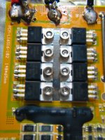
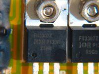
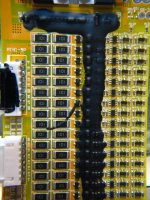
Thank you.

The intermittent charging only occurs when the circuit board is touched @ the zener and near by (~5mm near-by) zener(?).
I was not able the examine the back of the board last night but will shortly.

Cordially,
Tom
 
Whats up with the black crap dribbed on like icing on a cupcake? What's it function in life?
 
whatever said:
the mosfets on the board irf3077 are high amp , if genuine you could put alot of amps through them

Thank you! While discharging at ~20 to 23.88 amperes (max according to "watts-up") the mosfets got warm (no measurement at this time) after about 30 minutes at this rate of discharge.
Looks like all the tabs are common grounded. Would it make sense to attach a larger heat sink. I have some small u-channel aluminum that could be attached.

Tom
 
the zener is how the current gets to the transistors that turn on the mosfet gate current. if the zener has a bad connection, (looks like it overheated from a cold solder joint making intermittant connection), then there would be no charging while the mosfets are off, then when you push it down and it makes contact with the trace underneath, the transistors turn on and the mosfets turn on and then it charges. that is what you were seeing in your utubey thingy. the sealant is impervious to everything such as solvents or knife, but you might be able to put your soldering iron on the end cap of the zener and see if you can get the sealant to shrink back as you do that and then put some solder on the end and see if it will go down through the crack between the end of the diode and the sealant as it shrinks, to the trace on the pcb. or the solder still on the pcb may remelt and make contact again. push down on the zener while removing the iron. push with tiny screwdriver or pick. that may reset it in the solder as the solder cools again. too much heat for too long will not help, but it may be all you can do.

but there are better BMSs around too.
 
You might try to improve those solder joints on the power mosfets. Or are they soldered ok to etches on the bottom of the board?

A few of them look cold; for example the top leg of Q1B, and the middle leg of Q1D. That could make an intermittent problem like in your video. The solder should flow smoothly onto each surface, but looks to be a blob on the leg where the etch was not hot enough for the solder to flow.

The SMD soldering looks good on the board.
 
Thank you Dnmum and Ev99saturn.

I'll fire up the solder gun tonight!

Everyones help is greatly appreciated.

Regards,
Tom
 
if you can get a knife or razor blade over the end of the zener so that you can pop some of the sealant away from the diode on that end, then you might be able to see and get solder down to the pcb. but that stuff is impossible.
 
sorry made a mistake its 3077irf mosfets are the high amp ones, 3307 i'm not sure what the max amps is, hence why they are getting warm,
if they were 3077 you would be able to put a huge amount of amps through. I think those fets might be similar to p75n75 ( common type used in controllers) type so not really for high amp draw. Did a quick search couldn't find much info on them.
 
redstone02 said:
dnmun said:
why did you say it looks good?

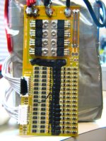
no info on the BMS or charger.

remember, these guys do not normally assemble battery packs. there is no documented report of how the pack is assembled and how they make the interpack connections and the sense wire connection.

the packs in the picture were taken on someones kitchen table. professional kitchen i guess.

i think cwah did buy a pack from them so ask him.

surface shipping will be less.

Looks like a tiled factory floor to me... maybe if a wok or egg-roll or even a bowl of egg drop soup was in the photo I would agree.
Looks good as in an assembled A123 pack; no buying parts from all over world to get a A123 pouch battery pack, looks good from that standpoint.
Cellman is out of stock at this time.
The darkside is drawing me in... this may I may keep from buying LiCo...
Thanks for the tip re: cwah!

Regards,
Red
You'd find a wok in a Chinese kitchen, but never an egg-roll or egg-drop soup. Those are made for us Americans.
 
The whole problem with your pack will be the copper cable they tried to solder to aluminium. pull it very gently and it will come off.

file.php
 
LOL! Yep, mine did the same. It was found while trouble shooting the "short" and was fixed with a mechanical connection. The BMS's short was still a problem. The pack also got a "puffer" in cell 16.
 
Spent some time on the pack today. Got it ~90% complete. Enough to "hot wire" it... bypassed Watts-up and on-off switch.
Got some cell logs. Other than mismatched cells, I am still learning how to glean information from the data:
 

Attachments

  • 20130121 Group 1 Discharge Charge.jpg
    20130121 Group 1 Discharge Charge.jpg
    87.5 KB · Views: 772
  • 20130121 Group 2 Discharge Charge.jpg
    20130121 Group 2 Discharge Charge.jpg
    86.4 KB · Views: 772
Hope it is OK to link some photos... If not please delete.
http://endless-sphere.com/forums/viewtopic.php?f=14&t=46714&p=690987#p690987
 
Back
Top