anpaza
10 W
- Joined
- Dec 7, 2010
- Messages
- 69
Thought it would be good to warn anybody who's going to buy a BMS.
Recently a friend brought his battery (16S LiFePO4 A123 "20Ah" cells) because it lost some capacity. With the nominal 18-19Ah it supplies only 15Ah after several months of everyday usage. He was blaming the battery to have a bad cell.
After inspecting the battery I discovered that it was simply disbalanced, and all the cells were in good state. The bottom four cells were sligthly discharged (that's because the logic part of BMS draws current from them) and the 10th cell also was a bit discharged, compared to the rest.
But how that happened, he used a BMS with balancing circuits?
Upon inspection of the circuit I came to the conclusion that the "balancing" function of the BMS is purely decorative and doesn't really work.
So I thought it would be good to warn everyone about it so that bad quality BMS producers will get what they deserve.
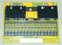
Here's the BMS picture:

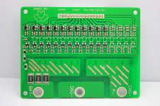
Here's another (green) variant of it, the reverse side:

The technical details, if anybody is interested.
Most cheap BMSes use cheap battery monitoring ICs used in notebook batteries and alike. Those ICs usually contain two voltage comparators, one for "overvoltage" and another for "undervoltage". The BMS that was in my friend's battery used Epson S-2861 ICs, with the "overvoltage" threshold of 3.9V (for LiFePO4) and "undervoltage" of 2.0V. Both limits have a hysteresis, in our case 0.1V for "overvoltage" (e.g. it disables charger at 3.9V and re-enables it when voltage drops to 3.8V) and 0.3V for "undervoltage" (e.g. disables load at 2.0V and enables when voltage rises to 2.3V).
Now this IC doesn't supply a third comparator that is needed for "balancing". So most cheap BMSes will contain yet another small IC (usually a TL431) that compares cell voltage to a relatively high, but lower than "overvoltage" limit (usually something like 3.6V) and when the cell voltage is over that limit, it will enable a small load on the cell (the large black rectangle 100 ohm resistors you see on the picture above, labeled "101"). This should allow all overcharged cells to be slowly discharged (all at a time) until the voltage on the most charged cells drop below 3.6V, allowing less discharged cells to catch up.
So I was interested to see why the balancing resistors are present on the above BMS, but they don't work as expected. And guess what... they use the "overvoltage" signal from S-8261 to enable the balancing load! Yes, saving a few cents per every BMS (on TL431 and two resistors), hurray!
So, the BMS "work" like that: suppose you charge the battery and some cell reaches 3.9V (ouch!). When this happens, the S-8261 will signal to disable the charging channel (one of the two groups of power MOSFETs). And at the same time enable the balancing resistor. Then the cell will slowly discharge to 3.8V (which took about 30 minutes in my case) and after that the "balancing" will be finished. Got it? Only one channel at a time - the first cell to reach 3.9V will be discharged to 3.8V and that's all the "balancing" that the BMS does. Then charging process resumes again, some other cell reaches 3.9V and the cycle repeats.
If you happened to be one of those unfortunates with such a BMS I would suggest to rise the charger voltage to 3.8V * number_of_cells (60.8 volts in my case) instead of the "standard" 3.65*number_of_cells for LiFePO4. But I won't suggest to do this for lithium-polymer, because charging them to 4.3V is dangerous (and the Li-Po variant of this BMS uses an "overvoltage" of 4.3V, ouch again!).
Also another thing that may help a little bit is to solder additional resistors in parallel to balancing resistors. I have soldered a 100 Ohm resistor on top of every balancing resistor and thus shortened the length of the "charge to 3.9V - discharge to 3.8V - enable charger again" cycle about twice. So, if you sometime leave the battery on charge for all night, that may compensate the accumulated disbalance, if it is not too large. This won't work with every charger, though - some models will turn off and never turn on again until you pull the plug out of the wall outlet.
Recently a friend brought his battery (16S LiFePO4 A123 "20Ah" cells) because it lost some capacity. With the nominal 18-19Ah it supplies only 15Ah after several months of everyday usage. He was blaming the battery to have a bad cell.
After inspecting the battery I discovered that it was simply disbalanced, and all the cells were in good state. The bottom four cells were sligthly discharged (that's because the logic part of BMS draws current from them) and the 10th cell also was a bit discharged, compared to the rest.
But how that happened, he used a BMS with balancing circuits?
Upon inspection of the circuit I came to the conclusion that the "balancing" function of the BMS is purely decorative and doesn't really work.
So I thought it would be good to warn everyone about it so that bad quality BMS producers will get what they deserve.
Here's the BMS picture:

Here's another (green) variant of it, the reverse side:

The technical details, if anybody is interested.
Most cheap BMSes use cheap battery monitoring ICs used in notebook batteries and alike. Those ICs usually contain two voltage comparators, one for "overvoltage" and another for "undervoltage". The BMS that was in my friend's battery used Epson S-2861 ICs, with the "overvoltage" threshold of 3.9V (for LiFePO4) and "undervoltage" of 2.0V. Both limits have a hysteresis, in our case 0.1V for "overvoltage" (e.g. it disables charger at 3.9V and re-enables it when voltage drops to 3.8V) and 0.3V for "undervoltage" (e.g. disables load at 2.0V and enables when voltage rises to 2.3V).
Now this IC doesn't supply a third comparator that is needed for "balancing". So most cheap BMSes will contain yet another small IC (usually a TL431) that compares cell voltage to a relatively high, but lower than "overvoltage" limit (usually something like 3.6V) and when the cell voltage is over that limit, it will enable a small load on the cell (the large black rectangle 100 ohm resistors you see on the picture above, labeled "101"). This should allow all overcharged cells to be slowly discharged (all at a time) until the voltage on the most charged cells drop below 3.6V, allowing less discharged cells to catch up.
So I was interested to see why the balancing resistors are present on the above BMS, but they don't work as expected. And guess what... they use the "overvoltage" signal from S-8261 to enable the balancing load! Yes, saving a few cents per every BMS (on TL431 and two resistors), hurray!
So, the BMS "work" like that: suppose you charge the battery and some cell reaches 3.9V (ouch!). When this happens, the S-8261 will signal to disable the charging channel (one of the two groups of power MOSFETs). And at the same time enable the balancing resistor. Then the cell will slowly discharge to 3.8V (which took about 30 minutes in my case) and after that the "balancing" will be finished. Got it? Only one channel at a time - the first cell to reach 3.9V will be discharged to 3.8V and that's all the "balancing" that the BMS does. Then charging process resumes again, some other cell reaches 3.9V and the cycle repeats.
If you happened to be one of those unfortunates with such a BMS I would suggest to rise the charger voltage to 3.8V * number_of_cells (60.8 volts in my case) instead of the "standard" 3.65*number_of_cells for LiFePO4. But I won't suggest to do this for lithium-polymer, because charging them to 4.3V is dangerous (and the Li-Po variant of this BMS uses an "overvoltage" of 4.3V, ouch again!).
Also another thing that may help a little bit is to solder additional resistors in parallel to balancing resistors. I have soldered a 100 Ohm resistor on top of every balancing resistor and thus shortened the length of the "charge to 3.9V - discharge to 3.8V - enable charger again" cycle about twice. So, if you sometime leave the battery on charge for all night, that may compensate the accumulated disbalance, if it is not too large. This won't work with every charger, though - some models will turn off and never turn on again until you pull the plug out of the wall outlet.


