
Hi, Combinations seems OK, so i am thinging about your sensor wheel, on photos it doesnt look like tooth and space between tooth are equal wide, and on video with leds, it seems to me that some leds at start of tooth is not fully light up, Do you have schematic of that IR Gate PCB ? do you have there any schmitt trigger logic gate ?
You are using an out of date browser. It may not display this or other websites correctly.
You should upgrade or use an alternative browser.
You should upgrade or use an alternative browser.
Water cooled car alternator
- Thread starter stepus
- Start date
monette999
1 W
- Joined
- Dec 22, 2020
- Messages
- 63
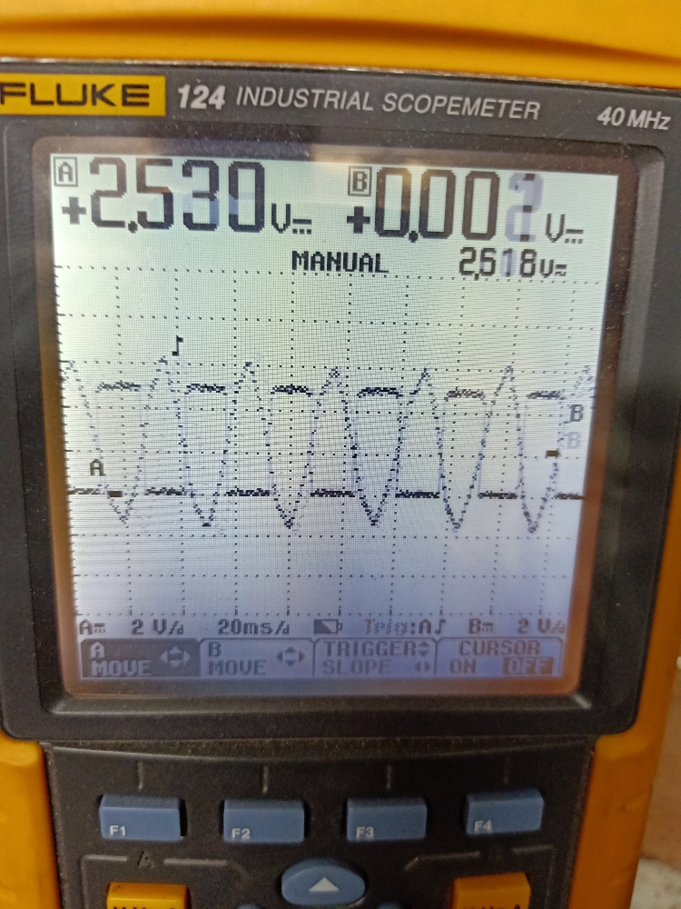
Well I made some progress by trouble shooting.
It looks like my female sensor connectors needed some TLC. I engaged them out of the house and bend the latch back. Now they are tigh and have solid connections.
The other things I did I swapped the sensor order.
From YGB to BGY. That works now and gives me constant start. No lock up anymore.
My duty cycle of the sensor signal is 50%. That is perfect.
Attached the pdf.
I hope on my test the next day I will have a smooth start.
Greeting
Gesendet von meinem CPH1911 mit Tapatalk
Attachments
ShadowNightmares
1 W
- Joined
- Nov 24, 2019
- Messages
- 63
monette999 said:Well I made some progress by trouble shooting.
It looks like my female sensor connectors needed some TLC. I engaged them out of the house and bend the latch back. Now they are tigh and have solid connections.
The other things I did I swapped the sensor order.
From YGB to BGY. That works now and gives me constant start. No lock up anymore.
My duty cycle of the sensor signal is 50%. That is perfect.
Attached the pdf.
I hope on my test the next day I will have a smooth start.
Greeting
Gesendet von meinem CPH1911 mit Tapatalk
That is an excellent news update, i always like to see alternator-powered builds going nicely
But how much did it costed? (Controler+disk+sensors)
monette999
1 W
- Joined
- Dec 22, 2020
- Messages
- 63
I paid 70€ for the 3000W Controller and 10€ for the Sensor System.
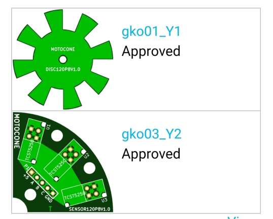
DIY
The PCB I have ordered at JLCPCB in China than 3x 1206 SMD 270R resistors and 3 Vishay Infrared Sensors.
That's it.
Alternator was 20€
So now I will check it the torque ist acceptable.
Greetings
Robert
Gesendet von meinem CPH1911 mit Tapatalk
DIY
The PCB I have ordered at JLCPCB in China than 3x 1206 SMD 270R resistors and 3 Vishay Infrared Sensors.
That's it.
Alternator was 20€
So now I will check it the torque ist acceptable.
Greetings
Robert
Gesendet von meinem CPH1911 mit Tapatalk
ShadowNightmares
1 W
- Joined
- Nov 24, 2019
- Messages
- 63
monette999 said:[...]
That works now and gives me constant start. No lock up anymore.
[...]
I hope on my test the next day I will have a smooth start.
[...]
I would also love to see a video of you showing the alternator starting up and revving
monette999
1 W
- Joined
- Dec 22, 2020
- Messages
- 63
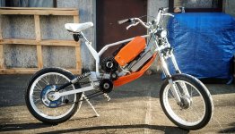
https://youtu.be/0ooEO186VR0
Hi the good think is that it runs fast
50km/h was my top speed.
The bad thing my bad starting behavior it not solved
https://youtu.be/UIsWZSbUQpA
Here my sensor system tests
https://youtube.com/shorts/LnO_8D1NlPE?feature=share
Greeting
monette999
Gesendet von meinem CPH1911 mit Tapatalk
Hi the good think is that it runs fast
50km/h was my top speed.
The bad thing my bad starting behavior it not solved
https://youtu.be/UIsWZSbUQpA
Here my sensor system tests
https://youtube.com/shorts/LnO_8D1NlPE?feature=share
Greeting
monette999
Gesendet von meinem CPH1911 mit Tapatalk
ShadowNightmares
1 W
- Joined
- Nov 24, 2019
- Messages
- 63
monette999 said:[...]
The bad thing my bad starting behavior it not solved
https://youtu.be/UIsWZSbUQpA
[...]
Hmm, that "cogging"/"locked rotor feeling" i already saw before.
YT user Enrengineering suffered from the same condition until his chinese no-name motor controller broken
So he tried a 3-part miniseries to get the correct placement for the hall sensors
https://www.youtube.com/watch?v=vxB4py8-NN0
https://www.youtube.com/watch?v=BKLhO-DoQuI
https://www.youtube.com/watch?v=7k-nG_keh1A
(This last one is where he got the better position for the sensors)
But he only gor the issue finally solved with sensors and a new controller (BAC-0501)
Just pay attention how led's work at video that previous member post. There's always two led's on, or, in every step of rotor, one led is turnd off.
Second: dont forget that alt insted of "classic" bldc motor, have much less steps in one rotation. In my setup (controler + alt), minimum rotation where controller start to speen alt, is 2 rotation for 1 second. So, there will never be nice and easy startup,....but,... If you supply big current for stator (70 amp's and more), and put minimum 5A in rotor, and most crucial, very easy on throttle, alt will always start (with jerk), but start, even on step hill.
Very easy on trottle, I mean give alt time to ketch up with speen.
Add simple electronic to the throttle output, and smooth the rising voltage from throttle.
monette999
1 W
- Joined
- Dec 22, 2020
- Messages
- 63
What wrong with my sensor test?
https://youtube.com/shorts/LnO_8D1NlPE?feature=share
I have added in each motor phase an 1R 10W resistors. The usage of the resistor was a fail
I will check if the cogging is driven by the controller.
https://youtu.be/-TYzTO_Dq9Q
Do you see the reverse rotation of the motor before it starts to turn forward. Is this driven by the controller. Why is the first pulse in reverse?
This is a difficult question?
Who can help?
Greeting Bob
Gesendet von meinem CPH1911 mit Tapatalk
Sorry, my mistake. In this video, at 10:30 is showing how led's work.
https://youtu.be/rQy-hIMY__A
For reverse step when starting, I blame bad position of hall sensors, or even that controller doesn't see sensors.
In those cases, controller will start maybe forward, maybe backward, until with befm realize position of rotor and rotor direction rotation.
If you are serious about your build, it's better to put sensors inside stator (like I did).
Attachments
ShadowNightmares
1 W
- Joined
- Nov 24, 2019
- Messages
- 63
Bane66 said:Sorry, my mistake. In this video, at 10:30 is showing how led's work.
https://youtu.be/rQy-hIMY__A
For reverse step when starting, I blame bad position of hall sensors, or even that controller doesn't see sensors.
In those cases, controller will start maybe forward, maybe backward, until with befm realize position of rotor and rotor direction rotation.
If you are serious about your build, it's better to put sensors inside stator (like I did).
Hey, how would i know the best position for the sensors inside the alternator?
It's still enigma for me, but,...
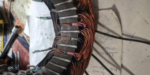
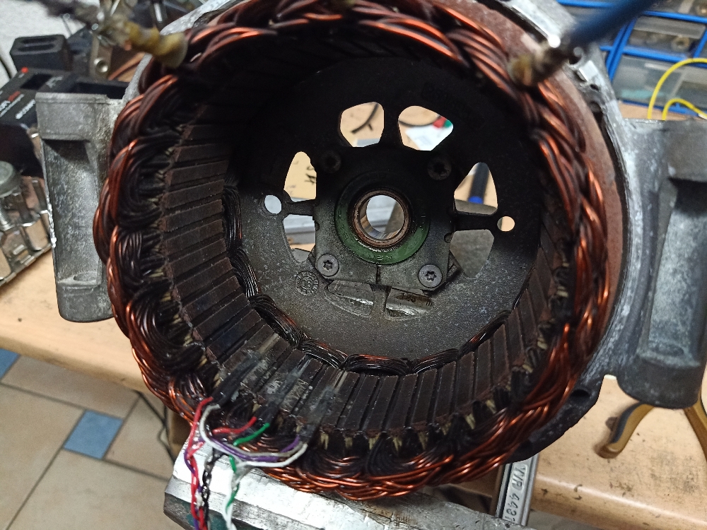
Watching many pictures, and locating center point where rotor is locked with stator (N to S magnetic) for each of tree phases, I install hall very similar what you see on the picture.
To determine center for each phase, you can track windings or energize with small current rotor and also energize one of tree phases. Rotor will move end stop (lock) in the center of that magnetic field. Do that for rest of phases, and you will know those tree centers for each hall. Sensor will be placed above wires (left or right) of that center point on stator. Left or right, I'm not sure, that is enigma for me.
Attachments
monette999
1 W
- Joined
- Dec 22, 2020
- Messages
- 63
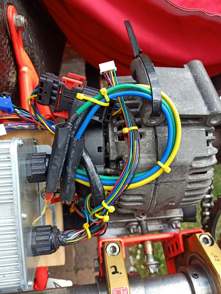
I can adjust my sensor position with the external system.
I can position my sensor. I have also tried the hall internal but I have so small slot's. Damaged the Stator windings.
Who is using a Sabvoton or Kelly controller and give feedback about start up ability.
Thanks for the interested chat.
Im considering changing the controller. But is that the solution?
Greetings Bob
Gesendet von meinem CPH1911 mit Tapatalk
monette999
1 W
- Joined
- Dec 22, 2020
- Messages
- 63
Dear all,
I have found the problem with the cogging.
It was an problem with the sensing order.
Now I can confirm that a Cart can run with 67V max 30A with an 3000W controller. Top speed is around 45 to 50 km/h.
Reverse is also working as well.
That's cool to have reverse gear.
I like to increase the voltage to max 84V.
So no need to buy a Sabvoton or Kelly controller.
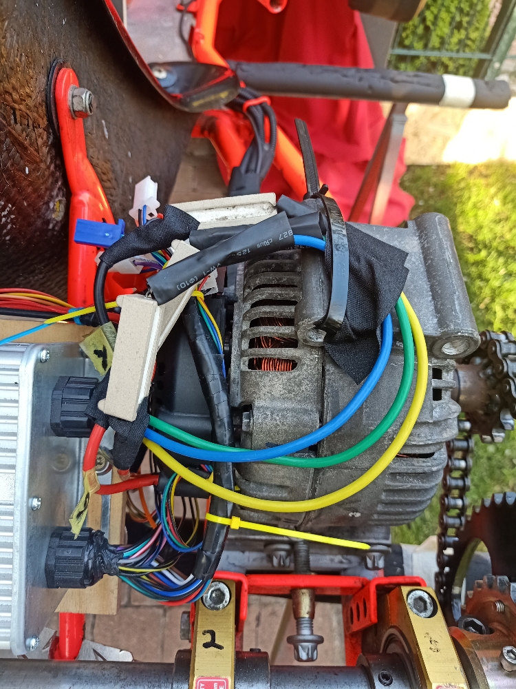
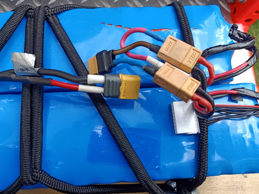
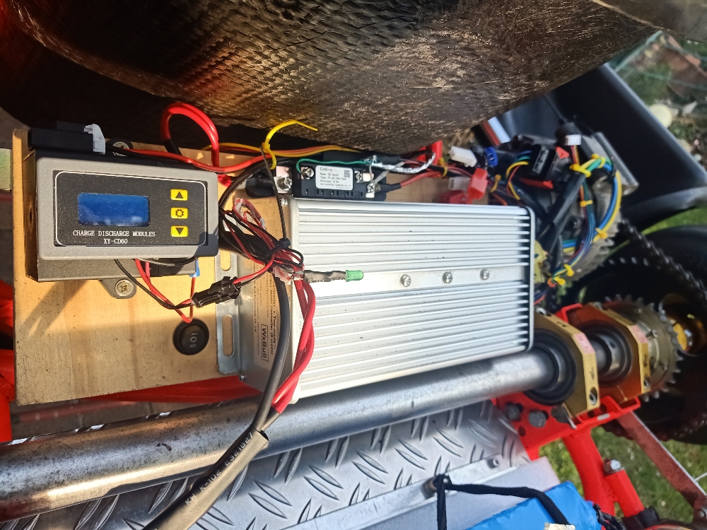
What is important is to pick a bigger gauge on silicon wire for the battery pack. See pictures.
What is also important to use a good connector for the sensor system.
The original connectors on the controller are really bad quality. The original connectors showed intermittency.
These are my findings.
Next project will be an offroad cart for my nephew.
Basis knowledge is now available.
Happy Day.
Greeting.

Gesendet von meinem CPH1911 mit Tapatalk
I have found the problem with the cogging.
It was an problem with the sensing order.
Now I can confirm that a Cart can run with 67V max 30A with an 3000W controller. Top speed is around 45 to 50 km/h.
Reverse is also working as well.
That's cool to have reverse gear.
I like to increase the voltage to max 84V.
So no need to buy a Sabvoton or Kelly controller.
What is important is to pick a bigger gauge on silicon wire for the battery pack. See pictures.
What is also important to use a good connector for the sensor system.
The original connectors on the controller are really bad quality. The original connectors showed intermittency.
These are my findings.
Next project will be an offroad cart for my nephew.
Basis knowledge is now available.
Happy Day.
Greeting.
Gesendet von meinem CPH1911 mit Tapatalk
How do you supply power for rotor? Going faster can be achieved with lowering current for rotor, but not too much (less power).
Maybe kelly have output for field weakening.
My experience says, from start to maybe 3/4 max speed, current min. 4.5A. For faster rpm's, around 3A (maybe 2 - 2.5).
Give some data of that battery pack's
Maybe kelly have output for field weakening.
My experience says, from start to maybe 3/4 max speed, current min. 4.5A. For faster rpm's, around 3A (maybe 2 - 2.5).
Give some data of that battery pack's
monette999
1 W
- Joined
- Dec 22, 2020
- Messages
- 63
Hi I have an 4s8p Lion configuration on my rotor. I have seen that others control the rotor current with a pwm controller for field weakening.
But that to ambiguous. How can I connect field weakening with my speed.
May drive battery is two 8s8p.
The cells are 2.9Ah and at 67V it pulls more than 30A.
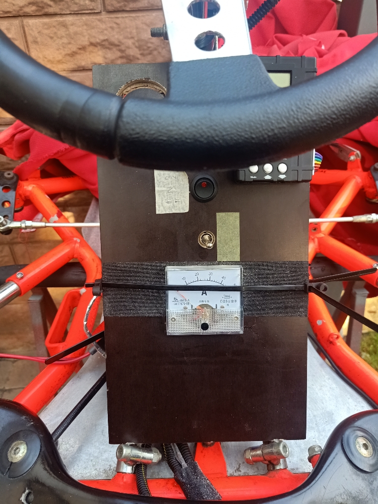
I have a now a shunt installed and my next trial will give me the max current by DOE.
So with 8P and 2C discharge I am at 46Amps. I still have some headroom.
My next trial ist to add 4p8S in seriel.
That I have a 20P8S.
Need to replace my cable to a bigger gauge.
I made the experience if my rotor voltage is going down that I have incident on power drift that I am loosing the magnetic connection between Rotor & Stator.
The cars weight is about 50kg plus my weight and my nephew, This adds up.
Like I said I have added a shunt and a classic analog meter.
Let's go
Greeting
Bob.
Gesendet von meinem CPH1911 mit Tapatalk
But that to ambiguous. How can I connect field weakening with my speed.
May drive battery is two 8s8p.
The cells are 2.9Ah and at 67V it pulls more than 30A.
I have a now a shunt installed and my next trial will give me the max current by DOE.
So with 8P and 2C discharge I am at 46Amps. I still have some headroom.
My next trial ist to add 4p8S in seriel.
That I have a 20P8S.
Need to replace my cable to a bigger gauge.
I made the experience if my rotor voltage is going down that I have incident on power drift that I am loosing the magnetic connection between Rotor & Stator.
The cars weight is about 50kg plus my weight and my nephew, This adds up.
Like I said I have added a shunt and a classic analog meter.
Let's go
Greeting
Bob.
Gesendet von meinem CPH1911 mit Tapatalk
ShadowNightmares
1 W
- Joined
- Nov 24, 2019
- Messages
- 63
monette999 said:Hi I have an 4s8p Lion configuration on my rotor. I have seen that others control the rotor current with a pwm controller for field weakening.
But that to ambiguous. How can I connect field weakening with my speed.
If you really want to connect the field weakening to the speed, one (more complicated but automated) idea is to:
Get a PWM controller with a digital meter for duty cycle or a PWM controller with a dedicated potentiometer, a microcontroller (Arduino), a way to sense the alternator RPM, digital meters for current in the battery and rotor
You will need to learn and save on a video how much of the rotor field you can lower at each RPM band (using the arduino and a screen to show the RPM) while you're driving it, so that you will have an idea on how to make it automated without losing too much torque at each RPM band but still having a bit more "stretch" for speed.
Let's suppose that: Below 1500RPM you let full torque, from 1500RPM to 2000RPM you can lower 6% of the field (1% @ 83RPM), then from 2000RPM to 3000RPM you can lower it 13% more (1% @ 76RPM), and 19% more from 3000RPM to 5500RPM (1% @ 131RPM), in total of 34% of field weakening in variable steps.
Then you will use the RPM sensing on the arduino to know when to start lowering the PWM duty cycle automatically using a digital potentiometer, that you can install in the place of the original potentiometer and control it with the arduino as well
ShadowNightmares
1 W
- Joined
- Nov 24, 2019
- Messages
- 63
monette999 said:Hi I have an 4s8p Lion configuration on my rotor. I have seen that others control the rotor current with a pwm controller for field weakening.
But that to ambiguous. How can I connect field weakening with my speed.
Or you can try a more easier solution, like the YT user Kouvpasir, that used a brushed controller and made it like a boost paddle for their kid's kart:
[youtube]ggnNzUkGSPI[/youtube]
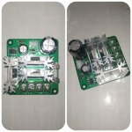
You dont have to be ambitious, just buy simple pwm for brushed motor. I'm using that. There's no need for different power pack for rotor. It's robust, and do the job.
Only one problem may occur. Because you set current for rotor with potentiometer, current will change accordingly to voltage dropping on battery pack. So, set desired current when battery is below half, and on full battery, you will have higher current, but not to much higher.
For me, when voltage is 65 - 66v current is on 5.3A, and on 53v current is 4.5.
I'm not expert with later electronic, but with this pwm and arduino to change resistors instead of potentiometer on pwm, geting higher or lower rotor current can be nicely achieved. Changing current can be than related to rpm's, or (for advanced users), arduino can use voltage from shant in controller (0 to 100mv), and to have big current in rotor when you push throttle, and getting smaller when throttle is closer to minimum.
.... Or, maybe both (rpm's and shan't voltage).
Maybe (I hope), maybe someone who reads those post, and know to writhe sketch for arduino with those parameters,...
Attachments
for supplying current to rotor, its better to use constant current. When i was measuring standstill torque mentioned above. I have seen that stator field is inducting to rotor coil. So I saw on the power supply that was set to constant voltage a current drops when i was powering stator coils... By this its better to use some DC-DC buck converter in CC mode - current can be set by arduino, or by potentiometer. DC-DC converter in CC mode - i thing some LED driver can do the job. And control program for arduino will be easy, to write, or maybe easier will be using OPamps, comparators etc. Decreasing current based on measured RPMs is very easy and arduino is maybe a overkill.
monette999
1 W
- Joined
- Dec 22, 2020
- Messages
- 63
Can I use my Sensor Signal as speed information for pwm field weekening?
What hardware shall I use?
Some adruino which can control a pwm Controller?
Who can provide the software program.
Last time I was programming ist 30Years ago?
Grüße Robert
Gesendet von meinem CPH1911 mit Tapatalk
What hardware shall I use?
Some adruino which can control a pwm Controller?
Who can provide the software program.
Last time I was programming ist 30Years ago?
Grüße Robert
Gesendet von meinem CPH1911 mit Tapatalk
Similar threads
- Replies
- 1
- Views
- 488
- Replies
- 4
- Views
- 777

- Replies
- 0
- Views
- 804
- Replies
- 4
- Views
- 1,574