-WAYNE'S TADPOLE TRIKE-

waynebergman

100 kW
Joined
May 7, 2011
Messages
1,016
Location
Pender Harbour British Columbia Canada
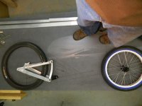
working materials.jpgbba2.jpgbba1.jpgView attachment 1I have been dreaming about building a tadpole trike after I first rode a Catrike at a dealership a few years back. I have purchased build plans from A-Z for there Warrior trike and feel this is a good starting point for what I am wanting. As I have a surplus of misc bike parts, a welder and a lathe so I should be able to make something that will work and also keep the costs down.

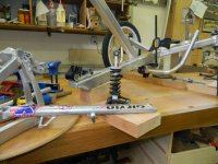
Plans are to use mostly 6061 aluminum for the construction and some mild steel for the steer tube, crown, brake calliper mounts and steering linkage. I have several old full suspension frames in the spare parts pile so I plan to use the rear swing arm off of the Norco shown in the attachments for an inch or two of travel on the back end of the trike.

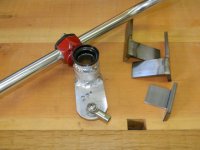
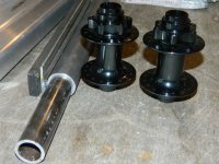
To date I have ordered some 20" BMX rims,20mm axle front hub, spokes, & tires for the front wheels, I have purchased my needed aluminum and steel stock shown in the photo attached here. I also plan to use the rear 24" electric wheel from my Giant xc mountain bike to start for this bike, and if it works well I will get a second electric rear wheel dedicated to stay on the bike.

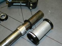
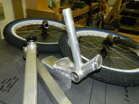
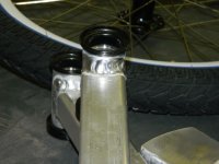
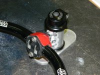
Also shown in the photo here is the 1.5" OD aluminum tubing that has been bored out at each end for a press fit to my thread less head set cups and the bottom bracket shell assembly that will be an adjustable bolt on to the main boom of the trike.

Please feel free to comment on things that are heading the wrong way as I post my progress photos. I have read the A-Z plans over about 5 times and starting to understand implications of castor, centre point and Ackerman steering etc but trikes are new to me and I am sure I will need a lot of help during this build.

A few questions please......
1. Are there any forum members with a Warrior tadpole trike that has had a rear suspension substituted for the rigid assembly that is spec'd in the plans, and if so how did it work out?

2.Looking at some rear suspension tadpole models that I have seen in shops they appear to seem to have small suspension travel which makes sense I guess. I would want around 5" ground clearance under the lowest part of the frame when in motion so I am guessing without rider 6" ground clearance and then one inch of sag with my weight on board and then one more working inch of travel for when the bike is in motion but I am only guessing on these numbers?

3.Does anyone have a good explanation as to why these tadpole trikes as so expensive? Looking at the different models in the shops I feel they are way over priced compared to the value you get when purchasing a regular mountain bike. I am sure its because there are just not enough of these bikes sold but they are way too expensive in my opinion.
Any advise appreciated ........

Wayne
 
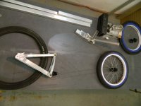
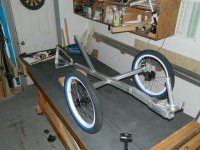
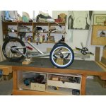
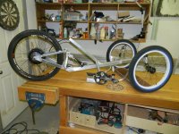
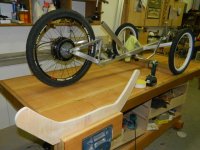
mock up o1.jpgmock up o2.jpgI have a different swing arm assembly I will be using now as the Norco rear triangle was not going to fit so good. The rear triangle is off and old MK Legend Banshee.

My rims, tires, and tubes arrived from http://www.chainreactioncycles.com/ca/en .These ship out of Ireland so its hard to believe I got the two rims, the tires and tubes all for $104.00 including taxes and free shipping to Canada. Only took two weeks for delivery. Spokes were close to 100 bucks from my local bike shop in Vancouver....OUCH! The 20mm hubs were a good deal at 30 bucks a piece also at the LBS.
 
I have the AZ Warrior plans, and others. I don't see why a rear suspension wouldn't work out fine if you follow other suspension geometries, which it looks like you are. The Voyager LWB recumbent (2 wheel) plan uses the rear suspension triangle from a box store bike, a "basket" type swing arm like what you have there with the shock attaching to the seat upright. Main thing, make sure the shock attach points are on the same arc of travel of the swingarm.

As far as the high prices, I think you're spot on that lower production numbers equal higher asking prices. If the big names got into trikes, maybe they could spread the cost across the product line, but then, their top models are approaching five digits already. And, I don't think there is enough demand for trikes to make high production runs viable.

Good luck! I'll be watching with interest.
 
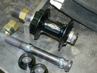
hub axles.jpgThanks Skynight

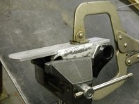
Shown here are my 5/8" bolts with a bit of build up of weld and then machined down to the 20mm for a nice snug fit to the hubs. The half inch flat bar shown just inside of the nut that is threaded onto the axle is for the axle tabs that will be welded to the steer tubes crown.
 
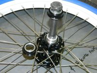
hub machining.jpgsteer tube&crown.jpgI thought I could go with out the dust caps on the hubs but I think they are the only thing holding the bearings in place so I just shortened the dust caps some and I will use them. Also shown in the photos here is one of the crowns that has been machined to accept the lower head set race. I will also fill this crown with a solid steel short plug before welding the crown to the steer tube, then comes the welding of the axle tab onto the bottom of the crown. This axle tab needs to be angled correctly to get the center point steering correct.
 
Wayne, your Ultimate Torque Arms are in the mail :wink:

Doc
 
View attachment 3oct15b.jpgoct15c.jpgoct15d.jpg
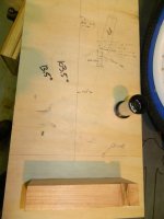
My approach for finding the center point steering was to figure out the offsets from center of the tire to the edge of the hub that the axle tab would sit against and some other figures like center of wheel axle to the ground and just placed the lines on a board and measured the resulting angle needed for the axle tab to sit at for the king pins to line up with the center of the tires contact point. Once I had this angle which was 103.5 degrees then I cut my 1/2" stock at this angle and also made up a welding fixture to hold things in place to keep me close to this angle for the welding process.
 
oct16a.jpgoct16b.jpg
Steer tube and work around to make the threadless head set work for me by cutting up an old MTB stem and boring out my steer tube for star nut is now completed. Looks like I am ready to start the 1.5" ali steering arms and also the rest of the frame construction.
 
oct22a.jpgoct22b.jpg
Steering arms and wheels sets complete with king pins done now. Time to start the main boom
 
oct 24 b.jpgoct 24 c.jpgoct 24 f.jpg
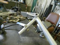
These compound cuts for the steering arms are time consuming to get right. My wood working bench that has a fairly flat work top surface and adjustable legs to level this surface is coming in very handy to place fixtures for holding and checking angles of all the parts.
 
oct 25 a.jpgoct 25 b.jpg
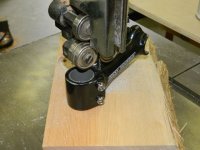
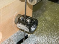
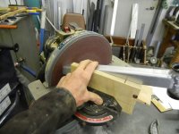
Thanks guys. It looks like I have got the symetry test passed for the compound cuts on the steering arms. When the two steering arms get flopped to each other and the cuts butted up tight to each other and then if two lengths of steering arms form a straight line you have got two arms the same. The little jig for the band saw also came in handy for cleaning up the parts on my 12" disc sander.
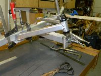
I will make a welding jig I think for holding the arms firmly in place while welding up the arms to the main boom. If I dont keep them locked in place during the welding and also while they cool I think everything will go all wongky and twisty. Taking some measurements today with the parts clamped up on my work bench I can see an easy way to do this so we will see how it goes.
 
Fixture for arms.jpg
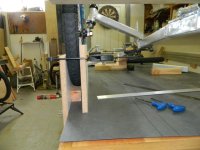
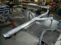
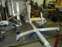
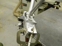
The fixture with the concrete anchor bolts sticking out the ends should help to get the steering arms in position and keep them somewhat in place during the welding process. It is not a very good picture I see, to show the workings of it but it has some angle stock welded to the fixture to keep things at 90 degrees to the main boom. I have a good feeling about this so far. I should be able to leave my woodworking bench now with this welding fixture clamped in place and move things over to the welding table and have at it. I am wanting this fixture to hold things in place but yet still let me spin and flip the main boom to help me get in an easy positon for welding.
 
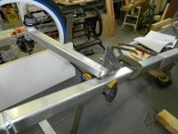
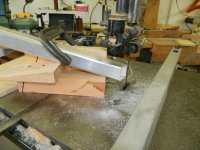
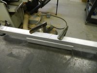
oct 30a.jpgoct 30b.jpgoct 30c.jpg Making more progress today. Machined some steel plugs for the aluminum pivot piece for helping with distortion issues when welding. As luck would have it I welded the ali pivot component and forgot to use this set of plugs. I am getting dumber by the day, I better hurry up and finish this thing.
 
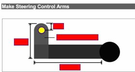
control arms.jpgI have blocked out the specs on the photo here as Atomic Zombie is not wanting any of the content from the plans they sell for there trikes posted out on the net or shared. I want to use this photo to explain a question I have regarding the Ackerman steering details as I have changed my wheel track and wheel base from the stock plans and want to make sure I get the loacation of the connecting rods in the right place.


My best guess is if I draw a straight line from the king pin centers to the center of the rear drop outs (at the axle) and then take this line I have drawn and mark its path along the center of the control arms I should have the location of the hole center for my connecting rods? The yelo circle on the drawing attached shows the hole location I am trying to get in the right place. The reason I am asking this is I am not sure if it matters the distance from the king pins on route to the axle centers at the rear or as long is this hole location is on the path to the axle center?

Thanks in advance.....wayne
 
dr02.jpgdr01.jpgdr03.jpgdr04.jpg
I will glue the torque arms to the swing arm assembly before I weld the swing arm pivot to the main frame. I figure this way I can tweek the fit up of the rear pivot assembly if the torque arms get glued on out of square.

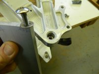
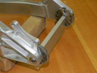
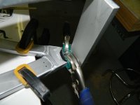
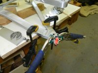
Shown in the photos here is a fixture to aid in placeing the torque arms level and square to the swing arm. I will do one side at a time to ensure nothing goes wrong. The fixture is just there to help clamp the torque arms symetricaly in place. After the epoxy is applied to both surfaces of the ali and the steel and the clamps are on, I then remove the fixture and spread more epoxy on things and let it sit over night. Tomorrow I will do the left side in the same manner.
I also cut some thickness off of the stock DrBass TA's as I am going with placement of the TA's on the inside of the chain stays for both sides. As my Banshee MK1 rear triangle is a 150mm spacing and the mac motor axle is 135mm I have gone with a 7.5mm thickness for both TA's. I have dished the wheel with drive side spokes 2mm shorter than the non drive side to pull things in center of the swing arm. This swing arm is sysmetrical unlike my Giant DH so you need to dish the little mac hub a good 1/4" to the drive side.

After the TA's set up I will use the 10mm openings on the TA's to cut out the aluminum so the wheel's axle can slide into place.
 
ussa.jpg
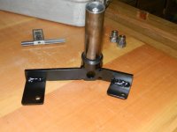
Under seat steering assembly. I have used a seat post binder to keep the profile low of the overall assembly and welded the stem right on to the head tube. The aluminum steer tube and ali crown was welded right to the plate shown on the bottom of this photo so I can just rivet this to the underside of the main frame for the underseat steering. Two SS rivets should be enough as there is not a lot of stress on this assembly. I will keep an eye on it and if it shows any signs of movement I will weld it in place.
 
gervin lr.jpgThese old Girvin forks from the parts pile have lots of aluminum linkage bits that will come in handy for mounting its shock onto the trike. These forks must be 25 years old. If I remember right these linkage type forks were used on the old Pro Flex full suspension bikes back in the early days. I had been saving these forks thinking they would make a nice street cruizer one day but it is too late for that now. I have no idea how this will work for me wanting just the two inches of rear suspension travel but I can always use the shock mounts as they are and just get the right shock for it down the road if this does not work right.
 
wheel on lr.jpg

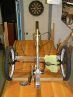
I think the swing arm mount, the DR Bass TA's, and the shock mounts will all work. I actually got to sit on it today just to get a feel for if the suspension would work as I hoped for sag and travel and I think I am close enough to go with it for now. Its very uncomfortable sitting on that 2" square tubing for long so it was a very quick test. It appears I will have good space for the 50v 14.3ah pack just tucked in behind the back rest. I will also place the controller in this area as well.

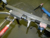
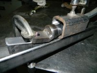
Next comes the Ackerman steering details and the linkage for the under seat steering.
 
two.jpgthree.jpgfour.jpgone.jpg
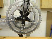
The 50 tooth sprocket I salvaged from a bike at the dump a while back was off a road bike and its bolt pattern was not going to match the MTB crank assembly I am using on this project so I cut some of this sprocket up so it would fit around the crank arms and then used rivets to attach it to the Race Face 36 tooth sprocket and cranks.

The steering bits seemed to have worked out good.

I will move on to the seat construction now.
 
Back
Top