What controller do I have?

j bjork

1 MW
Joined
Aug 31, 2018
Messages
2,288
Location
Linköping, Sweden
And the next question, what can I do with it? :wink:

I bougt a cheap, very chinease controller:

fCEZZ4hl.jpg


98g6JUsl.jpg


6j9xn0zl.jpg


4ms9c9el.jpg


od91QbYl.jpg


dTaXsEwl.jpg


hjMNWeTl.jpg


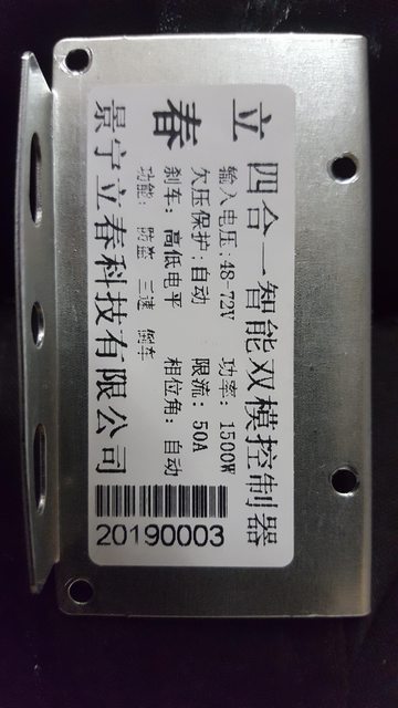
There are some instructions, but they are in "chenglish", or what is the word? Well, they are not in the best english anyway.
I don´t think the controller looks too bad, some soldering is not the best though.
I think I have been able to sort out the wiring, but it shoud have pas. But I can´t find it.

This controller is just something cheap I bougt to have something, until I get the right one. But it would be nice to get as much as possible out of it.

It should also have eabs (regen?), but I can´t find that ither.
There are solder pads for different voltages, but none are soldered.

PY95zBKl.jpg


I am going to use 20s lipo, should I solder the 72v?

There are a bunch of unused connections on the bord, can someone tell me what they are for?

f547GqUl.jpg
 
You have the 1000w 38A 36v/48v version outlined in thread below.
https://endless-sphere.com/forums/viewtopic.php?f=2&t=96736

I have two of these mounted up in our bikes.
They perform well.
 
You have two sets of jumper wires that when connected, enable something. black one wire connectors, in pairs.

One may be regen. Another might be self learning, but many controllers with self learn have all the same color wires on the phases. So maybe its something else, like a half power mode, or even a theft feature.

Try em and see.

Chances are your pas sensors are one of those other white plugs, unless its a generic scooter controller.
 
From what I can find, the jumper wires I have is for self learn and for cruise.
x and ds should be for regen/eabs. From the other thread:

"The "power and electric lock" function is straightforward. The heavy red and black are your main battery power, and the orange wire is the "ignition" which provides battery power to the actual controller logic.

Phase and hall wires are standard, as well. There's a group of pads on the PCB - "5V", "U", "V", "W", and "GND" all together. These are the red, yellow, green, white, and black hall wires, respectively.

The EBS brake wires are both grey and, when jumpered together, turn on the braking (or regen, if true) capability - provided the LVC and power source are compatible. These are connected to pads labelled "DS" and "X" on the PCB

The "high potential brake" (it's purple) is an input signal that would be used if this controller were used on a scooter. You'd connect this to the same 12V signal that drives the bike's tail light. It goes to "SH" on the PCB and has the same effect as shorting the low potential brake.

The low "low potential" brake (the one most of us actually use) is a black and white, going to "GND" and "SL", respectively. When shorted, this switches off motor power and activates EBS.

The throttle ("handle accelerator", as diagrammed) is red, white, and black. Red goes to "+4.3V", black to "GND", and white to "SD" - the latter being the actual throttle signal.

The "gear switch" is the 3-speed control. Black goes to "GND", grey to "K1", and white to "K2". Left open, the motor runs at its "medium" speed. Short black to grey, and speed is reduced to "low". Short black to white and you get full speed.

The "reverse function" (brown and black, going "DC" and "GND", respectively) reverses the motor when shorted.

The "cruise function" (blue and black, going to "Q" and "GND", respectively) holds your current speed when shorted.

The "autometer signal" is interesting. It seems analogue (though probably just buffered PWM). The faster you go, the more voltage you read on this line. What's weird is that it hangs out of the controller, unprotected and uninsulated, but ramps up as high as 18V when the bike is at full throttle on a 39V pack. It's blue, and connected to "S+". I have no idea how I'd use this, though driving a regular analogue panel meter could be fun. :)

There are two connectors for an alarm function - which I have NO idea about.

Alarm power (red and black) goes to pads marked "PS+" and "GND".

Alarm signal is three wires - Grey goes to "A3", white goes to "W", and orange just brings back out full battery voltage (it's directly connected to the orange "ignition" wire)."

I didn´t have anything connected to ds or x, so I just soldered them together.
There are no mention of pas, but I think those smaller controllers should have it at least?
I have found out what all af the connectors I have is for. Well I dont know how to use the alarm connectors, maby I will just get rid of them.
 
There is no regen (as in regenerative charging)....just e-brake which will slow you down, but all power generated is emitted as heat from controller and not fed back into battery.
PS: controller LVC is 33V....does not matter if pack is 36V or 48v. I modified mine so LVC is 31V (great for 36V LIPO).
 
Hey, i have just received this exact controller.

have you tested it in the end?

specifically for regen/eabs, ever figure out what that was? mine is also not wired or soldered together and i also don't have regen or eabs working.

did you figure out what soldering the voltage pads did? i presume you just jumped them.

for cruise control, have you tested that? it acts differently from my old controller. so far if i connect it at speed it will "cruise" but if i leave it connected it wont "cruise after holding for x time" unlike my old controller which cruised if i held throtle for 5 seconds. my wiring loom seems to link up a line to 5v, so i dont quite understand if i am supposed to pull up Q to 5V or ground it. if its a pull up then im good, otherwise im going to have to rerun wires.

thanks.
 
Back
Top