what min and max voltage YOU do with lipo?

I preffer using 4.15 to 3.4V no BMS

But I balance to 4.20 ocasionally.

3.4 from 3.0V is 0.4V margin so under load cells sag to 3.0 to 2.8 witch is just fine.

Doc
 
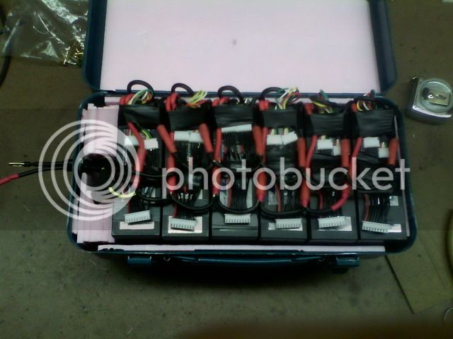
I do not use a bms but I often check each cell with volt meter. This is my pack of 12 hard case bricks (48 total cells). The 6 8s balance connectors are available so and I can check each cell with pokey probes.
50BatteryPack_zps6e81f63d.jpg


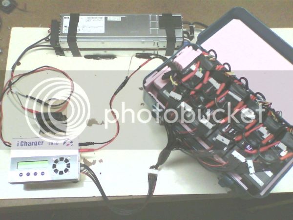
I have a harness that connects the the parallel cells so when charging I do not have absolute knowledge of each cell, but the charger does display the average of each group and I would see if one was lagging and would know to check each cell manually. This is my charging setup.
51Charging_zps9756b310.jpg
 
Hummina Shadeeba said:
wow Id have thought maybe 3.7 volts would be a minimum voltage but you're almost a whole volt under that. That's lower than anyone says. I still wish there was a study done and a graph to look at. I'm sure some people would say "never under 3" and here you are confidently saying otherwise. I'm just stewing on it because they still haven't arrived but I'm surprised at the ambiguity. I imagine letting a battery sink that low when not even under load it must hit much less than even that with a load. You're the only one I've come across with such a low number


With proper use, the cell limits are established by the manufacturer. With poor control, you have to build in a safety margin. This margin is worthy of debate, only as some people don't stick to the established methods the cell manufacturers expect us to use.

Manufacturers quote between 2.7V and 2.8V minimum. I could not get a figure for my HK Turnigy's. So I just presume 3V, as 3V is just scratching on the whelms of reality. Any higher and it's no longer a 3.7v cell.

As a bms watches each cell individually. You can take every last drop from your pack, knowing that the moment a cell hits empty, the bms will disconnect. So, it is safe to set limits like 3v or under.

If your disconnect is controller based, your not watching each cell individually. If I were to set a controller for 3v, it would be a 3v average. With any imbalance seen as individual cell voltages both over and under 3V. It is very easy to not get what you asked for.

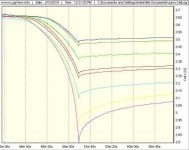
The graphs show a controller based lvc watching a number of different coloured cells. The controller want's 3.3V per cell. It's seen that when the average voltage is 3.3v, one cell has already dropped to 2.8V. This battery is just a random sample. Sheer coincidence shows us 3.3V at the controller is only just adequate. The next battery could equally be better or worse. Worse being under 2.8v when you asked for 3.3

It is mostly cell treatment causing the spread of replies. The cells are no mystery.
Just as with other kinds of lithium-ion cells, the voltage of a LiPo cell depends on its chemistry and varies from about 2.7-3.0 V (discharged)
Source: http://en.wikipedia.org/wiki/Lithium_polymer_battery
 
friendly1uk said:
Hummina Shadeeba said:
It is mostly cell treatment causing the spread of replies. The cells are no mystery.
Just as with other kinds of lithium-ion cells, the voltage of a LiPo cell depends on its chemistry and varies from about 2.7-3.0 V (discharged)
Source: http://en.wikipedia.org/wiki/Lithium_polymer_battery
I think the "spread of replies" is more the result of 2 different viewpoints.

"Empty" as:
1. The voltage that the battery sags to under throttle. (possibly as low as 2.80V - dependent on IR and Amps of drain)
vs
2. The voltage of the battery after drain removed and "real" voltage recovered - "static voltage".. (possibly 3.60V)

I tend to rate the empty voltage the same way I rate the "full" voltage ... in the static state.
My LiPo pack - 3.70V >> 4.12V
My 18650 Li-ion pack - 3.65V >> 4.05V
Using a step to next .02V, I measure the mAh required to raise voltage, chart and graph into a capacity map.
I use this capacity map to determine optimal full charge voltage and DOD (Depth of Discharge).
 
Depth of sag changes between users. Being related to pack size and C rating primarily, with many other variables like IR and state of charge involved. A reading taken after a pack has settled has little value. It doesn't tell us what it sagged to, and minimum voltages are our concern. Resting voltage is too loosely related to be scientifically useful.

I can't actually see what your running your lipo down to, which is the subject of the thread.

Two groups. Those doing it as intended, and the rest who have to use judgement.
 
friendly1uk said:
Depth of sag changes between users. Being related to pack size and C rating primarily, with many other variables like IR and state of charge involved. A reading taken after a pack has settled has little value. It doesn't tell us what it sagged to, and minimum voltages are our concern. Resting voltage is too loosely related to be scientifically useful.

I can't actually see what your running your lipo down to, which is the subject of the thread.

Two groups. Those doing it as intended, and the rest who have to use judgement.
Actually, seems the only way to encompass the variables.
With my LiPo at its "empty" of 3.70V I apply throttle to typical cruising speed, make note of voltage sag and use that as "my" LiPo's working voltage "empty".
"Empty", under throttle, with same cells would be different for every application and user.
The only commonality would be the beginning static voltage.
 
As this chart shows, different voltages have differing energy densities.
It also shows there to be minimal energy below 3.7V. (For this cell)

Additionally, charging past 4.25 seems pointless ...
Charging from 4.20V to 4.25V adds 5% capacity at a 29% loss of cycle life but...
Charging from 4.20V to 4.30V adds only 6% capacity at a 50% loss of cycle life!

file.php


Based on this chart, I would most likely Limit charge voltage to 4.10V for the ~90% capacity with 200% usable cycles.
Definitely I would limit the actual-static DOD to 3.7V.
Dependent on the pack size, formulation, controller, motor etc, this might entail a working DOD voltage of <3.5V.

Made a graphical representation of above current density data:

Small Lipo.jpg
 
An interesting observation:
With my battery at 3.80V, if I cruise at typical speed, voltage sag is to a moderate 3.73V (translated to cell level voltages)
However, with battery at 3.70V, if I cruise at typical speed, (additional throttle required), voltage sag drops to near 3.30V.

file.php


I say interesting because:
The voltage sag seems to cover a very similar area of current density!

Small Lipo C.jpg

This ... phenomena? ... would seem to indicate that any weaker cell, (or bank), would drop precipitously, at a possibly geometric rate.
So, if you insist on discharging deeply and you don't have LVC cell level BMS(?) protection, you should
get a cell level voltage monitor-alarm-cut off!

Personally, I prefer the idea of a slightly larger battery with more moderate charge and DOD voltages.
Safer, longer lasting and ... in the long run ... cheaper.
I leave enough safety margin and I do use the cheap bank level meter alarms.
So, I use no type of BMS and typically bulk charge ... with occasional balance charge.
I tend to set the alarm to a very generous 3.7V.
This allows me to limp home at reduced speed w/assist, while still not dropping below "my optimal" 3.70 static voltage.
 
Ykick said:
With a BMS I go 4.2V-2.8V. ... this was "under load"
Ykick said:
Majority RC Lipo users don’t really know what every cell voltage happens to be but they “assume” by way of “averaging” the pack voltage divided by # of cells in the pack.

Some of you know I’ve been playing with the old tried and true CellLog 8S, CA, power supplies, resistive (toaster oven) load, performing cycle tests, etc. Here’s a pic from logging an 8S section of my 20C 5Ah Turnigy hardcase 6S pack using roughly 1C discharge/charge rates. About 5A.
...
Everything drops very linear from about 4.2V until the steep knee about 3.65V. No surprise that’s the commonly quoted per cell LVC.

Trouble is, all we do when we set a LVC in a controller or CA is "assume" we have evenly matched cells at the same SOC. That usually works pretty good, until it doesn’t.

for the pack in my example here, if I were “deciding” on a controller/CA pack voltage LVC, I’d probably choose 3.3V/cell
...so if you plot the graph based on 3.65V/cell ... it’s obvious there’s less likelihood of taking any cell too low.

1-8DischargeZend.jpg
The apparent degree of variation between the cells in this pack and what this means with a BMS LVC of 2.8V is interesting. There have been quite a few different LVC policies presented here and somewhere in the discussion there is often a remark about the low effect on capacity as cell discharge drops off the knee. Ykick's plot suggests a little complication since many of the cells at BMS LVC are still just dropping off the edge and so have a bit more capacity to potentially contribute.

Although discharge curves showing voltage vs time are common, I hadn't actually seen any plots of 'capacity vs LVC cell voltage'. So --- Ykick forwarded the Logview data for his plot shown about and I massaged it a bit in Excel...

The plot below shows battery capacity vs LVC 'average' cell voltage. This mean voltage times the series cell count is what would be used for an aggregate battery LVC to achieve the same cutoff (as with a CA). Here we see the usable capacity increasing as we move to the right with LVC decreasing.

CapacityVsLvc3.png
  • Although the BMS LVC is kicking in at 2.8V/cell, the equivalent pack LVC is really ~3.21V/cell.
  • Setting the pack LVC based on 3.65V/cell drops the available capacity to about 91% of what it is at the 3.21V/cell setting.
  • Other 'capacity vs cell voltage' sample points are called out.
This is specific to Ykick's battery and whether that situation is atypical or not is open to discussion. However, it does show that even at 3.5V/cell, there is minimal loss of capacity (3%) and a fairly large margin (safer) for terminal cell voltage differentials at LVC. No surprisingly, the BMS approach gives the most usable capacity safely, but when running naked, even fairly conservative per-cell LVC values are not really too punishing from a capacity perspective. Also, the small change in capacity below 3.5V suggests that Ykick's cells are really pretty close in capacity in spite of the variation in terminal voltages.

Anyhow, just some results from analysis of a single pack - make of it what you will.... :D
 
At 1st glance these cells look to be badly differing in capacity.
Apparently a very low C rate discharge? 1C?
(Best cell voltage sag was only ~2-3 hundredths from 3.5V discharge V)
(.02V sag - compare to .28V sag at 2.8V >> recovered voltage)

file.php


But after looking at the minimal capacity below 3.5V, all cells appear to be within, possibly, ~3% of being equal in capacity.
If discharge limited to greater than a static 3.65V, pack looks to be of very reasonable usability.
(discharging to lower voltage causes faster deterioration.. limiting discharge to the point before voltage separation should help minimize the capacity divergence)

file.php


Update:
Using the timescale, based on when different cells hit 3.5V ...
3050 seconds ÷ 2925 seconds = 1.0427 so, best and worst capacity cells are within 4.27% of equal capacity.
 
DrkAngel's charts are very useful. I've found my Hobbyking Lipo are a little different, but pretty closely match what he's found. at 3.65v I have right at 10% capacity left, 1.5 AH left in a 15AH pack if I take it to 3.0v
I bulk charge to 4.15v, and balance charge to 4.2v. I never store a battery above 3.9v for more than 48 hours, and try to get 3.85

I aim to bring the bike home at 3.8 volts or so, which is around 30% left in my pack. That gives me a nice reserve if I need it, or say F@#$ it, and decide to go another few miles on the way home. I don't worry about taking the voltage down to 3.0 volts resting, but I try to avoid it. But if I do take the voltage down below 3.6v, I won't bulk charge it until I've had it on a balance charger.
 
My pack to date is 20s 10ah assembled from the ever popular 4s 5ah hardcase batteries. Permanently paralleled at discharge and balance taps in pairs, connected in series. For the first ~250 cycles I was charging to 4.1v and discharging to about 3.78v, charging in parallel @ 0.8c. I then bought another house which was a little further away, this required charging to 4.2v, discharging to ~3.75v, though on occasion as low as 3.62v depending on headwinds. I also upgraded to an Adaptto controller and now charge at 2c. I have now done another 280 cycles like this.

I charge just prior to use, 20 minutes before I leave I plug in and dump 1800watts into the pack, as a result the time spent at high SOC is very short. Perhaps this has assisted with longevity?

I have just run a discharge test on one of the batteries, 4s '10ah' and got 8.75ah discharging to a 2.8v cutoff (which bounces back above 3v once load is removed). When brand new on the same charger with the same test methodology I got 9.5ah, so 530x 80-95% discharge cycles has resulted in a total capacity loss of ~10%. Like other graphs shown, these batteries tend to show substantial deviations in cell voltage below 3.65v

Unfortunately a single cell is giving up, no longer charges above 4.05v and given the age and history of this pack it's not really worth repairing with a new brick. I figure I got my monies worth.
 
EDIT. the comments below refer to lithium cobalt.

Any of my comments refer to resting voltage, after say, 90 seconds off the throttle. It will come up even more after 10 min. But since sag increases so much when below 3.5v, I try to be in limp home slow mode by the time I'm seeing 3.5v. Once I'm seeing 3.5v under load, I'll start taking short stops to check my pack resting voltage.

If 10% is left at 3.65v, it's interesting to note that very little of that 10% is left below 3.5v. So Though you can run them to 3v, you aren't going to go that far on what's below 3.5v.

But very little of what? Typically people are running 10-15 ah size packs. When I go touring, I may carry 45 ah of 48v. The last 2% can still be 100wh, enough to get 4-5 miles at a slow speed!! It can seem like magic to get 5 miles from an essentially empty (3.5V or less) pack. With 45 ah hooked up, you can go slow and see almost no sag under load at the end, and run that pack down to the very bottom to make the next town with a plug. 14s, so you can ride till it's at 42v if you started out balanced.

Normally riding around town with a smaller pack I'd stop at 48v (3.4v) or so, and 90% of rides end up returning home with much higher voltage left. When I stop at 48v resting for 90 seconds or so, it will bounce back to as much as 50v later after more time resting.
 
^ Good examples on this thread showing that total pack capacity is important in determining a safe margin. With a larger pack, you can definitely get closer to the 'edge' with less risk and larger packs will have better longevity (all else being equal).
 
Drunkskunk said:
DrkAngel's charts are very useful.

They are wrong.


DA, when you say your cells are empty, they are 25% full still. You don't actually know your minimum voltage I don't think. The topic of this thread. You seem to have a method you might use to test it, but it's floored as it just measures sag at cruise.
 
I base my "full" and "empty" on "reasonable capacity".
Using a modded MeanWell S-150-5, I 1st discharged a representative cell to a static 3.30V.
With mAh meter attached, I increased the MeanWell in 1/10V increments and noted the mAh of capacity till voltage stabilized at set voltage.
Using this method I was able to accurately map the energy contained at various cell voltages.
Since my results were at the static voltages, I base all my calculations on resting (static) voltages

1/10V increments produced a very coarse, but telling,"map" of energy.
But and so ... I conducted subsequent tests in 1/50thV increments.
See - Capacity Mapping

I ran individual tests for each type of cell that I acquired.
Various LiPo (and 18650 Li-ion) ... I rated from ~3.5V to some just above 3.70V as the beginning region of good energy density.
 
3.3v has 25% left for lithium cobalt? Or are you talking about NMC? I'd say you are effectively done at 3.3v with lithium cobalt.

Previous comment edited to clarify I was talking about lithium cobalt. I thought Dark Angels graphs were also for Hobby RC lithium cobalt pouch cells.

As for the accuracy of anybodies graphs, my eyes just glaze over, I go into a brain freeze looking at more than one graph. My brain just works different.
 
dogman dan said:
I thought Dark Angels graphs were also for Hobby RC lithium cobalt pouch cells.

As for the accuracy of anybodies graphs, my eyes just glaze over, I go into a brain freeze looking at more than one graph. My brain just works different.

Winners Circle and WinForce2 graphs are the only RC Lipo I've tested.
WinForce 2 was the most surprising, for me.
It demonstrated good energy density to notably lower voltages than any other cells I'd tested.
Most remarkable was that a 3.50V to 3.90V duty cycle provided a 70% of rated capacity for a 800% cycle life!
 
dogman dan said:
3.3v has 25% left for lithium cobalt? Or are you talking about NMC? I'd say you are effectively done at 3.3v with lithium cobalt.

Previous comment edited to clarify I was talking about lithium cobalt. I thought Dark Angels graphs were also for Hobby RC lithium cobalt pouch cells.

As for the accuracy of anybodies graphs, my eyes just glaze over, I go into a brain freeze looking at more than one graph. My brain just works different.

No, he said 3.7v is empty in his opinion. 3.3v was empty on his graphs. Neither of which is true. Unless as you hint at, he is off topic talking about some other batteries.


As is obvious by now, people with tight control can set cell level lvc in line with the manufacturers data. People not sticking to industry standards pick a higher value, knowing cells will actually get lower, and how low is left to chance. No actual figures are know. Though from a very limited sample we saw 10% of cells at 2.8v when lvc was set at 3.33v. Showing just how well controlled a lot of peoples packs really are. Or are not, as the case is here.

3.4v calculated from pack voltage would give some margin, that may or may not be enough. Certainly people using 3.4 can forget any idea's about it lengthening pack life. Some cells are still dropping to nothing, so the pack will last no longer. However, more pack is still carried to accommodate a 3.4v lvc. Enough more to of paid for doing it better. Leading to less weight on the bike and more in the pocket.

Extremely few people here have any reason to not be doing it properly. Yet many go to the extra expense that doing it wrong usually requires. I really suffer when surrounded by fools, and this topic grates. So many people ignore every pack manufacturer, do it their own way, wasting money and getting less protection. Spend days of their lives swapping dangerous wires around pointlessly, then burn something to the ground. It's ducking ridiculous pretending your ebike is a radio controlled toy, and charging with RC stuff, that RC users are forced to use outdoors in flame proof enclosures.

I need to go for a walk...

But first.. I understand some people are just prototyping, Or can't afford to build a pack for a bike and leave it alone. Forced to keep cannibalising it for other duties, they get little choice. Others have so many cells it is hard to cater for them. Most have no excuse though. I might poll on it..
 
All type Lipo have differing capacity.
I did mention one type that I rated as functionally "empty" at 3.7V.
Other, I "rated" as substantial capacity down to 3.5V.

I recommend limiting discharge to the point before the cliff ... and in the case of this example, before the voltages "diverge" (46 min 40sec)
While this limits capacity to 92% of available, it is full voltage current rather than the sagging-pitiful voltage petering down to cut off.
46min 40sec = 92% discharged (2800)
50min 45sec = 100% discharge (3045)


file.php


Possibly more important, (when discharging to cell level cut-off of 2.8V))
While the best cell suffers a moderate 4.2-3.5V discharge-sag (.7V)
the worst cell suffers a 4.2-2.8V discharge-sag (1.4V)
hypothetically, this might deteriorate-damage the weak cell twice as badly as the best cell.

This would effectively, and reasonably quickly, lower the usable capacity of the entire pack below the 92% that I advocate.
 
For lithium cobalt, stopping at 3.7v resting is a good plan. But it's NOT empty by any means. There is quite a lot left from 3.7v to 2.8v.

I have no idea of the effect on lifespan, but I definitely find that I rarely need to balance my Hobby King batteries if I don't discharge below 3.7v. So building your pack size to usually not need that last bit is wise advice. Iv'e been advising this for years, for commuters to carry about 20% more than they will usually need. That's any kind of battery.

I get lost in a thread like this, who said what, when? I would agree that though there is still some more below 3.3v, it's not much unless you are carrying 40 ah. So not much benefit to trying to squeak the last bit down to 2.8v out of a 10 ah bike pack. Only about a quarter mile of range, that you could just pedal pretty easy. Take em to below 3v, I bet you will need to balance them. Easy with 4-6 packs. Not so easy if you have 20.

I definitely try not to discharge below 3.5v for my Hobby king packs. But like I said, on a tour, 10 miles to go from a town, I'll go much lower if I need to. 100wh more can make a huge difference then.
 
It’s obvious there’s not very much energy left and the voltage differences increase exponentially once these Turnigy RC Lipo cells drop below 3.5V. If I had my druthers I might even spec a BMS/PCM which used that LVC.

Unfortunately, most BMS/PCM manufactures who sell to end-users doesn’t wanna bother with much customization so if you wanna use a BMS/PCM on RC Lipo you gotta accept the “industry standard” values. And in my experience (daily rider) those values seem to be working fine. So, in answer to the OP - I trust the professional BMS/PCM manufacturers values. But, only if using a properly installed and working BMS/PCM.

The REAL reason for using a BMS/PCM on RC Lipo isn’t to squeeze every mAh out of them although that’s a welcome by-product. The compelling reason is for when the cells change via age and/or become damaged, or perhaps a charger voltage output unexpectedly increases.

In any of those situations there needs to be some method of alerting and/protecting before the problem gets out-of-hand. A mass-produced BMS/PCM appears to be as good of method as any to accomplish that task.

Running naked, using conservative “worst case” voltage values works. I’m evidence of those practices. For many years I’ve used and babied naked RC Lipo - gotta pretty good handle on it and have avoided any serious problems.

But, this past year running with BMS/PCM has been very enlightening while convincing me that if properly installed, it’s better with than without.

I know there’s a lot of “who shot Jon” and “contributions” running around in this and other RC Lipo threads but it’s literally a “volatile” subject so any awareness raised and practical information absorbed is a positive thing.
 
The typical BMS etc. LVC is designed as a safety device, limiting damage by preventing discharge voltage, at the cell level, before the point of catastrophic failure.
Not as a method of squeezing the last bits of capacity out of a pack.

Even the balance function is necessary only ...
to repair the imbalance precipitated from discharging too deeply or ...
to make up for defective (self-discharging) cells.

Moderate discharges, from a pack with banks of equal capacity, without any self discharging cells ... seems to never require any balancing.
Combine this with reducing charged voltage slightly and the use of cell level volt meter-alarm and I have - IMO - a much better protection system ...
and a battery pack that provides a muchly extended usable life!

I used PCBs (BMS) right from my 1st 10s LiPo builds (2008) but soon learned that it was a poor substitute for making the extra effort of:
testing for and removing self-discharging cells; and
measuring cell capacity and building banks of accurately equal capacity.

Perhaps ... it is just my pride at building quality Homemade Battery Packs ... but I now look down with disdain and view a BMS as a Band-Aid for a defective ... pack ... or operator.
 
Since it goes directly to the business of accurate 'health indicators' for BMS-managed packs, here's a bit more detail on the capacity variation between the BMS-managed cells in Ykick's data.

As mentioned above, the variation in termination times and voltages may initially give the impression that the cells differ more than a bit in capacity. DA suggested that based on time, the max capacity difference is in the neighborhood of 4%.

1-8DischargeZend-small.jpg
However, capacity is proportional to the area under the voltage discharge curve - time may be used as an approximation in the linear discharge region, but over-estimates capacity when the slope is pronounced (after knee). Unfortunately, because the BMS terminated discharge, we are missing data to the 2.8V cutoff level from all but the lowest voltage cell. Extrapolating the existing curves, this missing data appears as the blue areas in the image below. The various areas are directly proportional to the added capacity that would be available if each cell was allowed to individually run to the BMS cutoff voltage.

Although the data for the undischarged capacity is not available, the areas in question are similar to the same voltage regions of the lowest cell (red areas) - for which we have data.

CapacityDifference.jpg
Finagling the Excel calculations to use the capacity from the red regions as a substitute for the blue 'unused' capacity gives us these % capacity differences compared to the lowest cell:

1 - 0.00% - lowest capacity cell
2 - 0.16%
3 - 0.53%
4 - 0.68%
5 - 1.41%
6 - 1.53%
7 - 1.94%
8 - 2.32% - highest capacity cell

The cell capacities appear closely matched with a max differential of only 2.32% - arguably inconsequential.
 
Back
Top