mistercrash
10 kW
I had trouble with the motor on my scooter recently and after looking at different options, I decided to just go the easy route for now and replace it with the same thing from the dealer. So I have this extra motor lying around in pieces with two magnets that are damaged on it. I'm thinking that it's a good opportunity to learn about this motor and play with it a bit. So what can I do to make this 500 watt motor a little more than what it is right now. Any ideas other then replacing the broken magnets?
I have a few questions here, there's 46 magnets on the rotor/rim and 17 poles per phase on the stator. Isn't the amount of magnets suppose to be the same as the number of poles? Or are they just there to create some magnetic field and it doesn't really matter how many there are? I also noticed that the poles of the magnets are alternating, how is that important? The magnets are 45 mm long by 13.8 mm wide by 3 mm thick. If I was to replace all the magnets with 50 mm long ones, would that make a stronger magnetic field and help the motor? John in CR suggested ventilating like he did in here http://endless-sphere.com/forums/viewtopic.php?f=2&t=39773. This would be a good start but is there anything else that can be done to make this motor more powerfull or efficient or both?
Thanks and here's a few pics and a drawing with dimensions of this project motor.
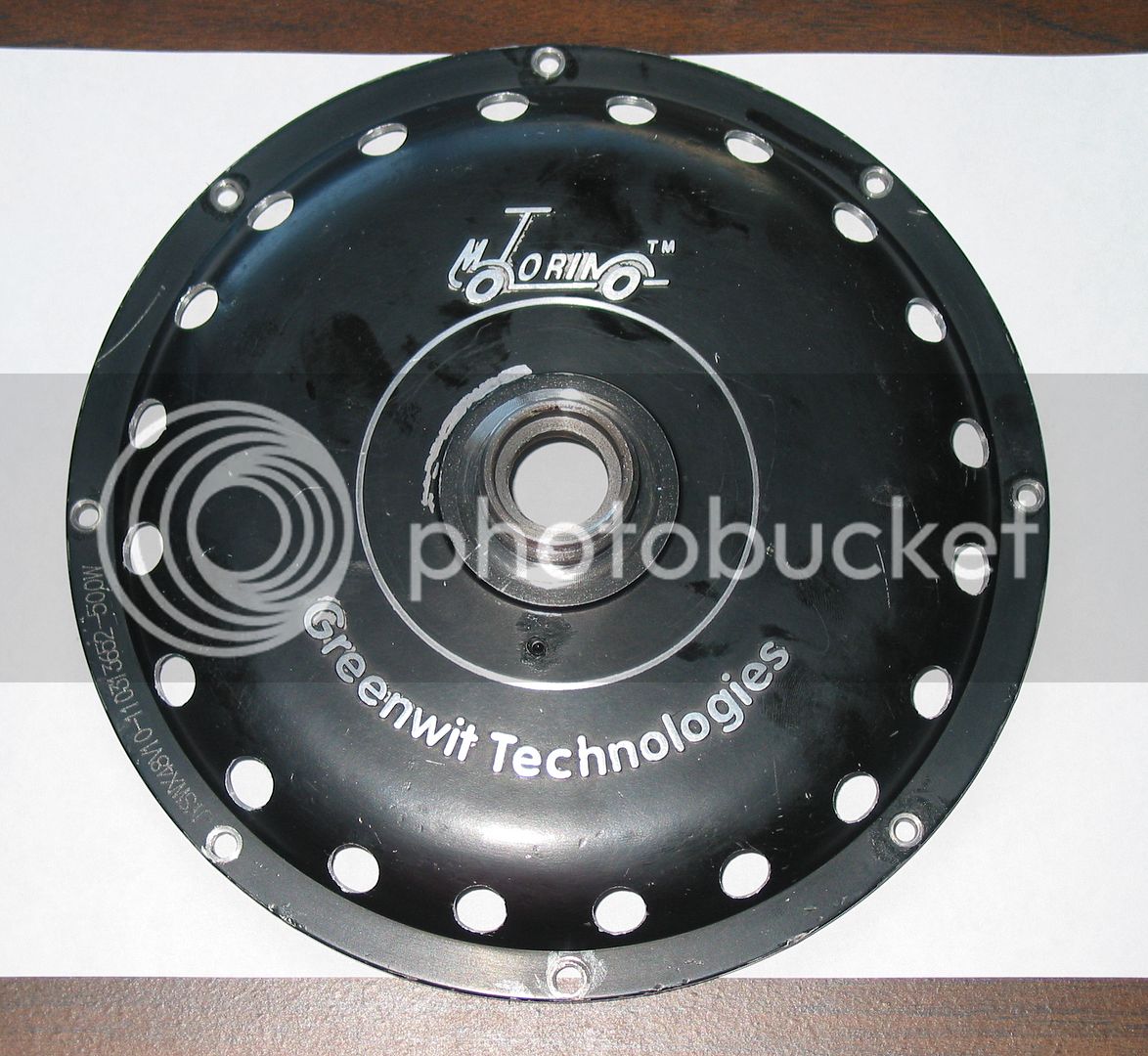
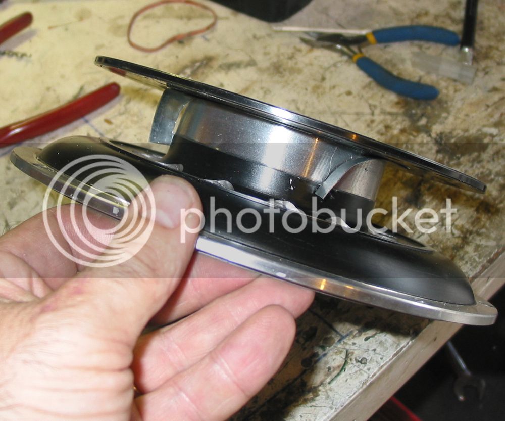
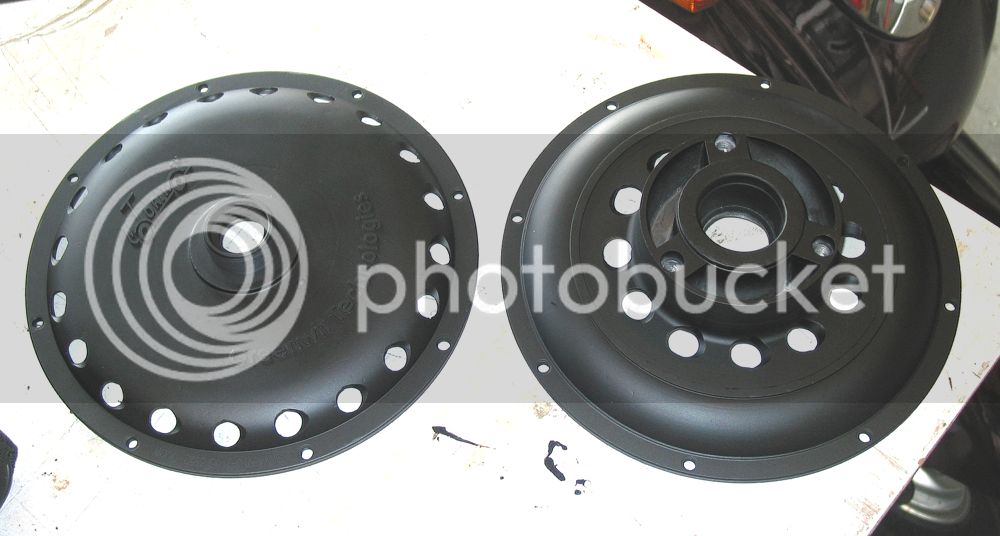
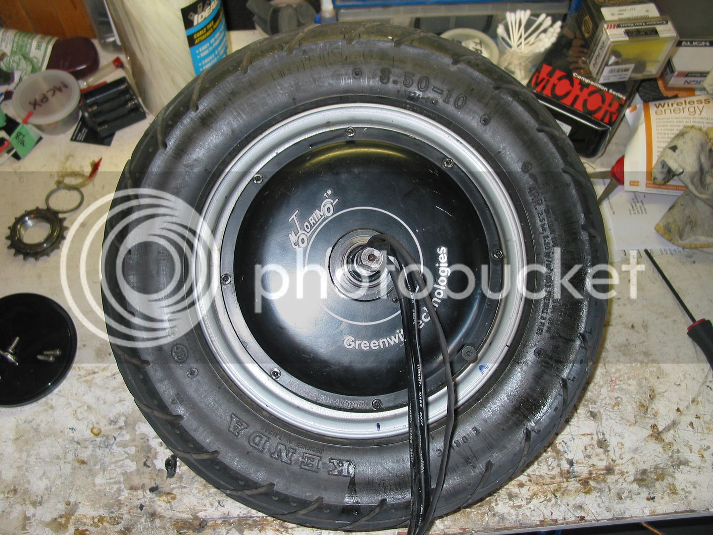
The one way sprocket side
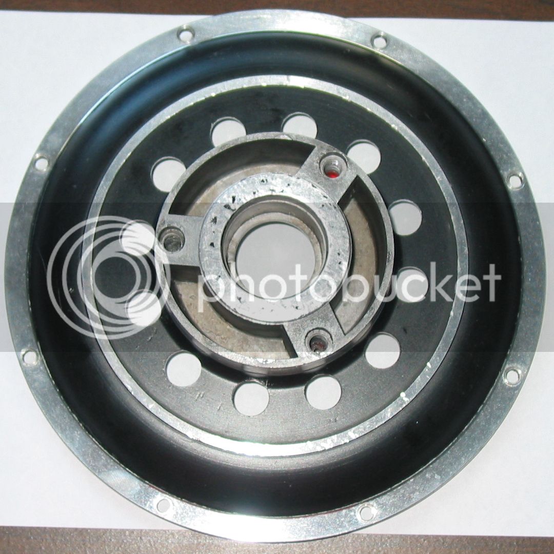
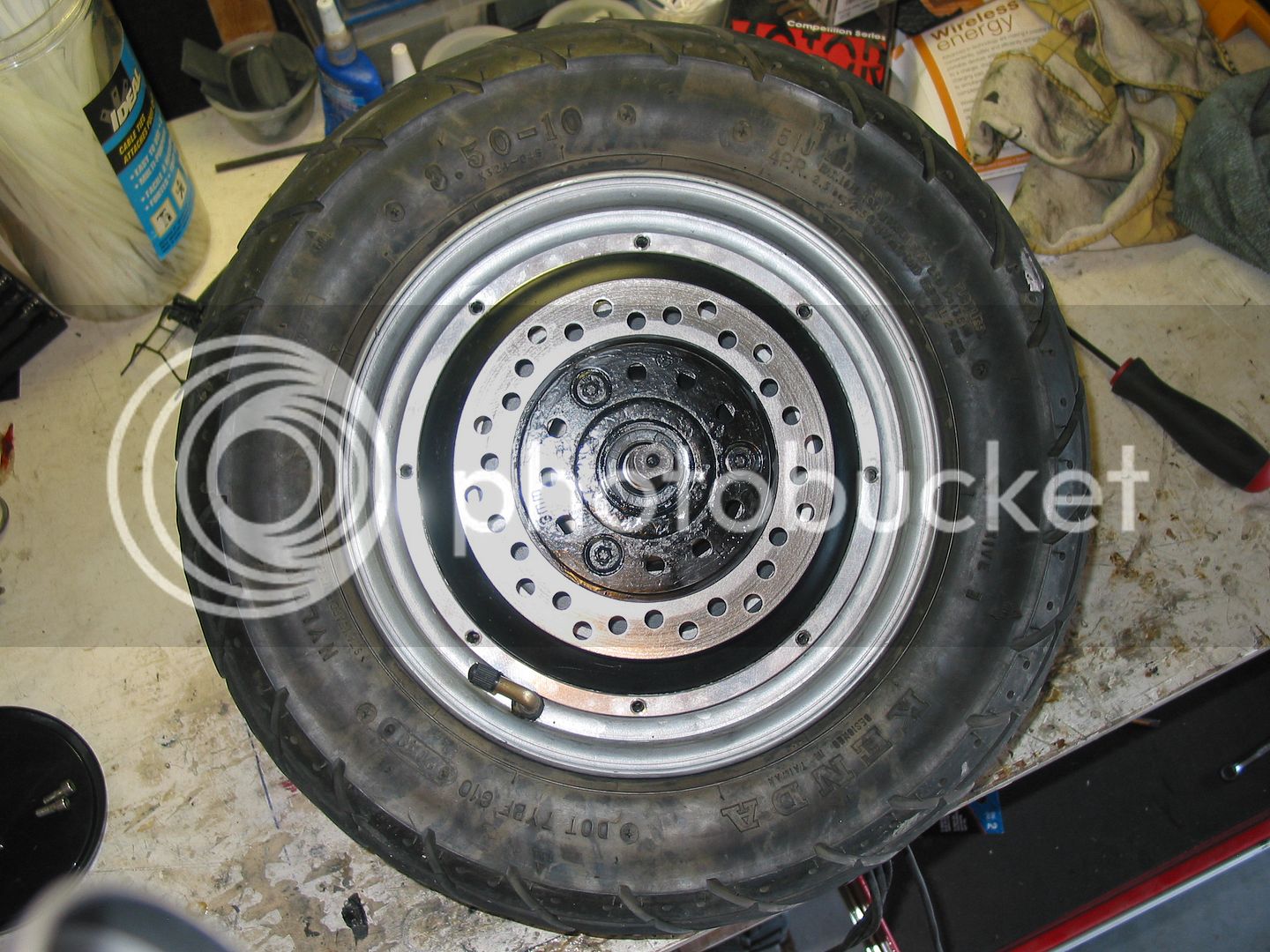
The brake disk side
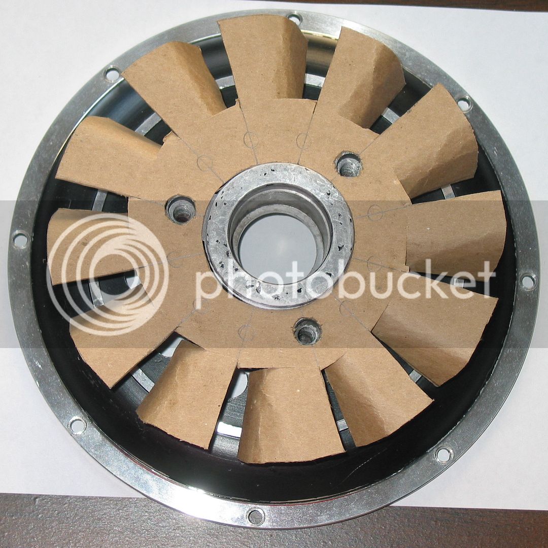
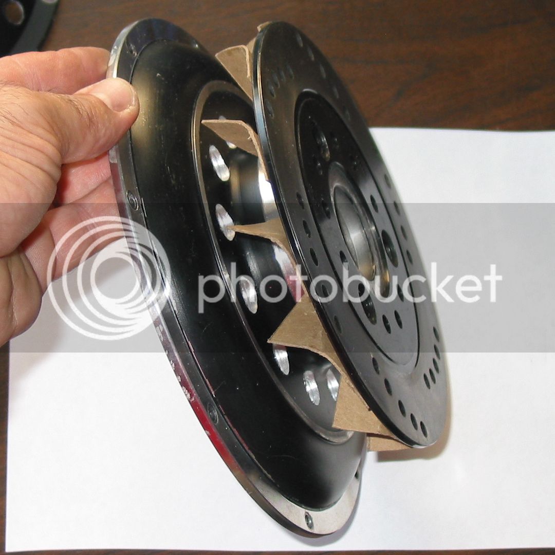
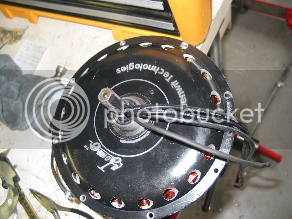
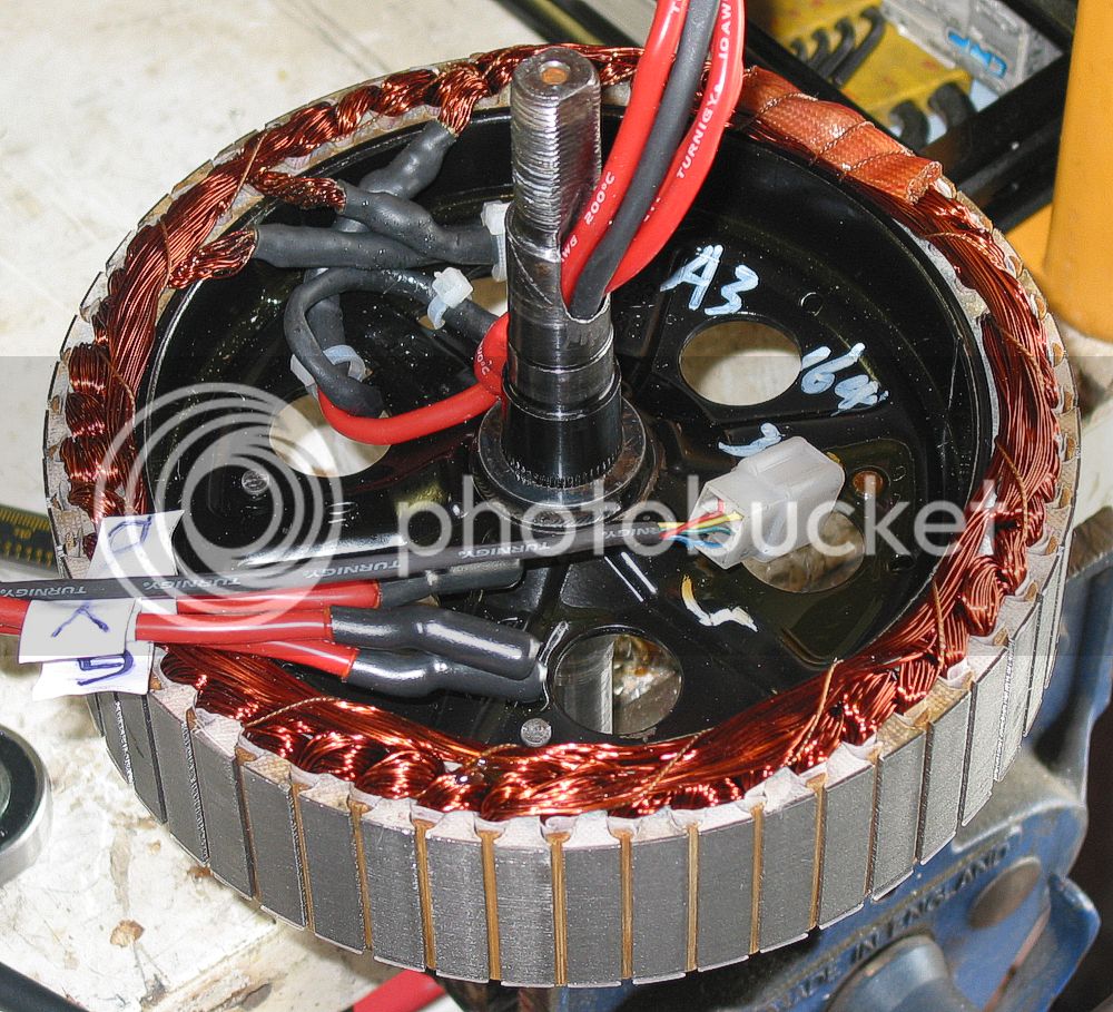
Without the covers
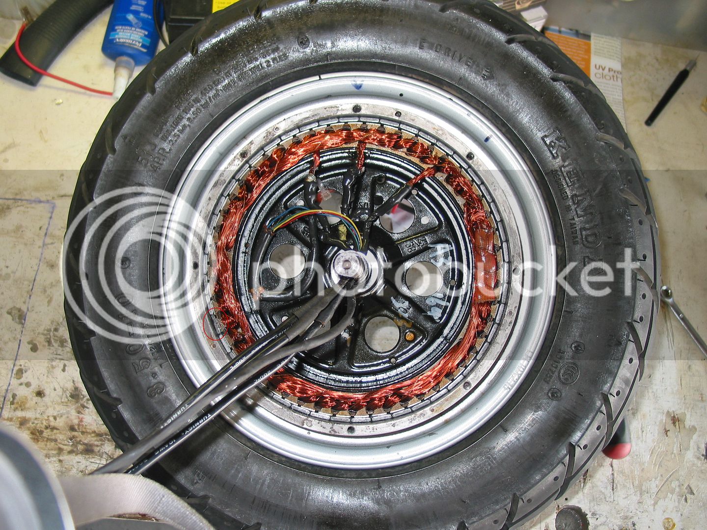
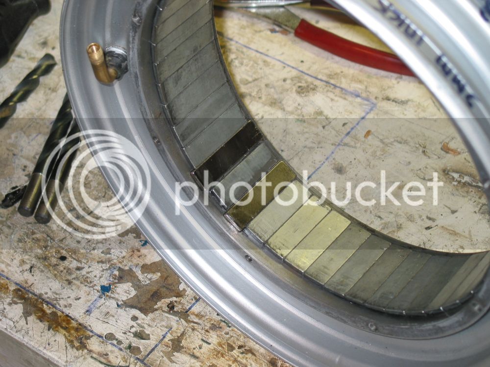
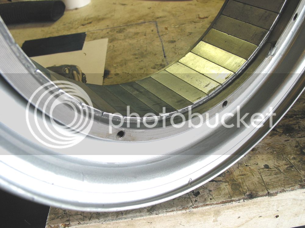
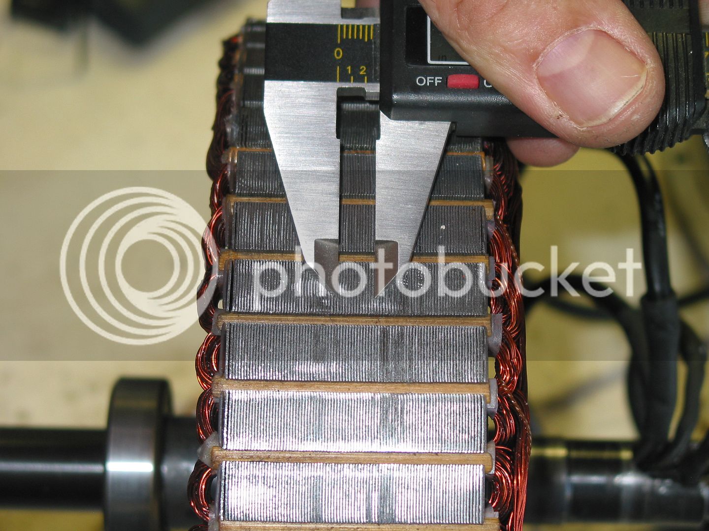
The laminations, the caliper is spread 1/4''. The stator is 45 mm wide
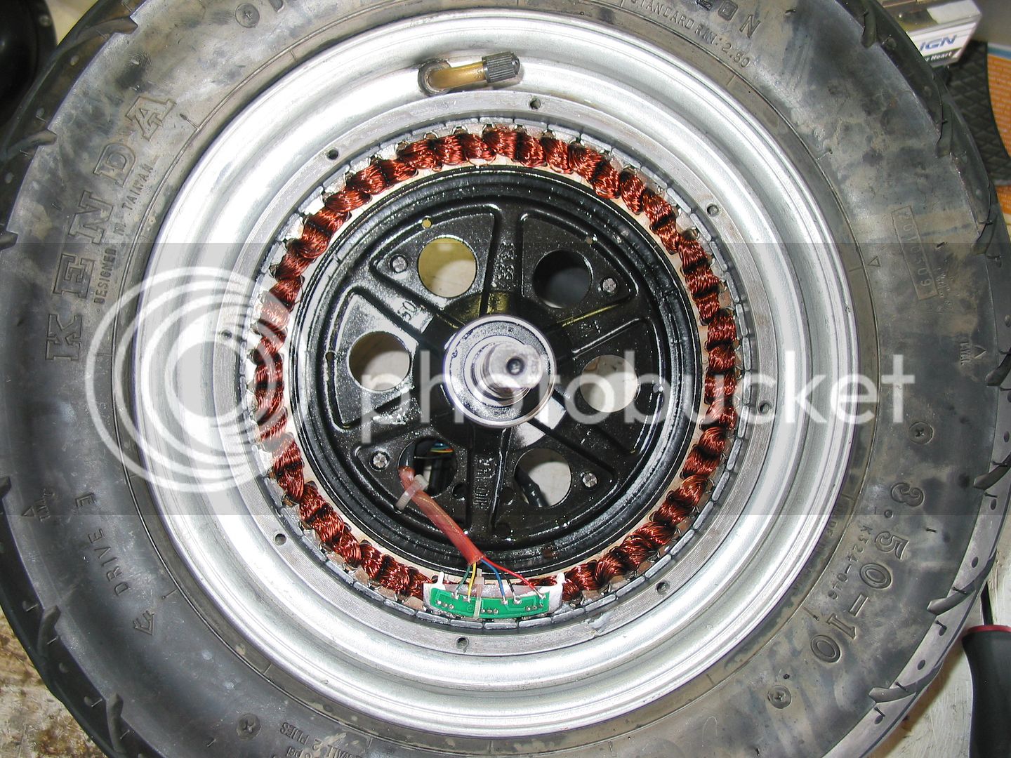
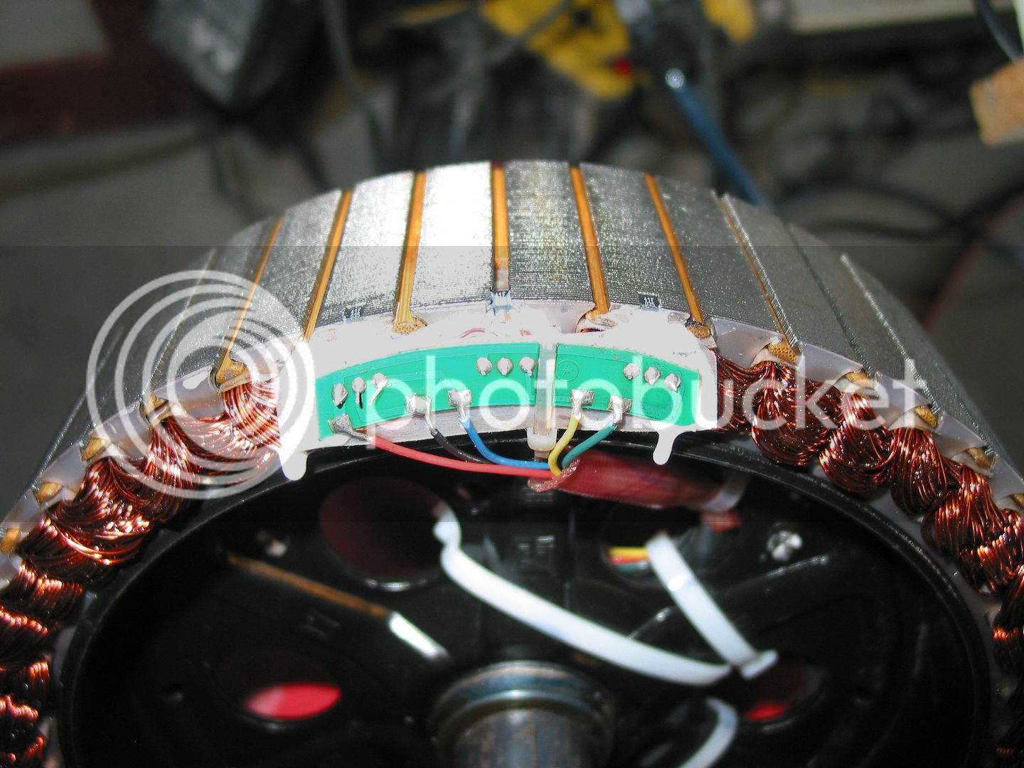
The hall sensors
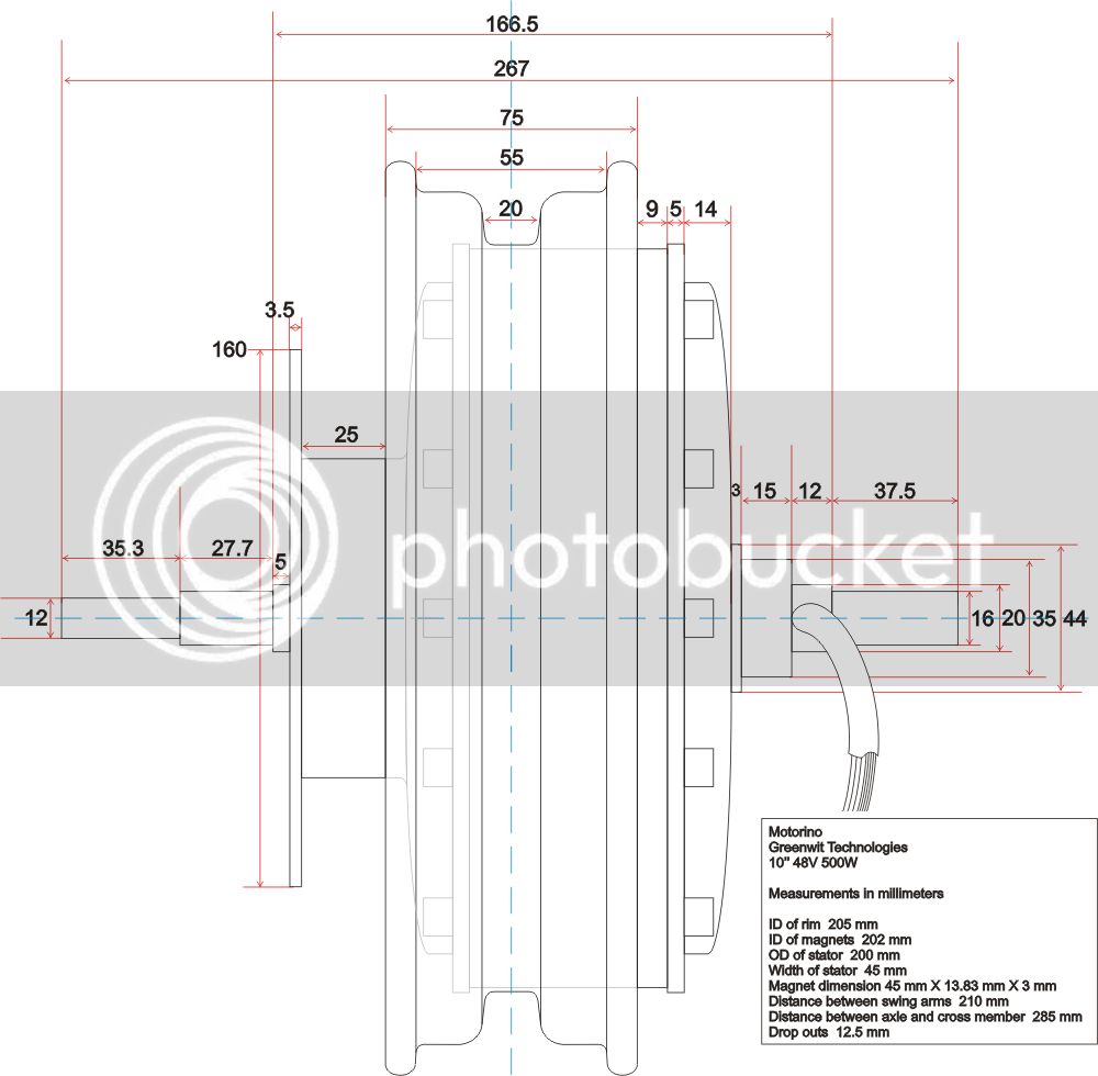
And a drawing with dimensions
I have a few questions here, there's 46 magnets on the rotor/rim and 17 poles per phase on the stator. Isn't the amount of magnets suppose to be the same as the number of poles? Or are they just there to create some magnetic field and it doesn't really matter how many there are? I also noticed that the poles of the magnets are alternating, how is that important? The magnets are 45 mm long by 13.8 mm wide by 3 mm thick. If I was to replace all the magnets with 50 mm long ones, would that make a stronger magnetic field and help the motor? John in CR suggested ventilating like he did in here http://endless-sphere.com/forums/viewtopic.php?f=2&t=39773. This would be a good start but is there anything else that can be done to make this motor more powerfull or efficient or both?
Thanks and here's a few pics and a drawing with dimensions of this project motor.
The one way sprocket side
The brake disk side
Without the covers
The laminations, the caliper is spread 1/4''. The stator is 45 mm wide
The hall sensors
And a drawing with dimensions
") I'm thinking it might help a little but the wheel doesn't turn that fast so I'm not sure if it's worth the trouble.
I'm thinking it might help a little but the wheel doesn't turn that fast so I'm not sure if it's worth the trouble.