Which controller for Turnigy 80-100?

Checking in to see if you figured out anything Burtie.

I spent the last hour on my rewound Turnigy 80-100. In Y I get the lowest no load amps with the sensors between Phases, ie. A & C. This way I got a no load at 24 volts of 1.64. With it between A & a the lowest I got was 2.10 amps.

Going to take a break and then try it in Delta
 
Drewjet,
other than amp draw, was it obvious which was the perfered set up? super smooth.....you know what i mean. :lol:
I am anxiousely waiting to hear your resultz....before gluing halls into AJ's & then my own turnigy motors.

I just took delivery of enough irfb3006's to mod a pr of these controllers:
http://cgi.ebay.com/ebaymotors/ws/eBayISAPI.dll?ViewItem&item=200488611604&viewitem=&sspagename=STRK%3AMEWNX%3AIT
We'll see if i can get any where near 10kw with this set up..... at 63v it shold burst 17kw before flashbulbing............i will try to get video of the melt down.... :twisted:
 
Drewjet and Thud,

I have not got around to doing anything practical with the theory yet, due to metal garden shed building :roll: (LiPo charging house for the winter) :)

You guys are at the cutting edge with these experiments, I eagerly await your findings 8)

Burtie.
 
I just tried delta and the best no load (3.84) I got was between a & c, which is also where I got the best no load for Y. Now I am all confused.
My best between A & B was 4.62 and my best between A & a was 4,88 but it had start up issues (sometimes no prob, sometimes I had to turn one notch.
 
Drewjet,

It would be interesting to test the currents with the motor running in the opposite direction (just re-jig the hall wiring combination). This would turn a 30 e deg advance into a 30 e degree retard and vice-versa.
 
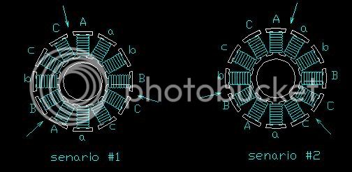
Just to be certain we are on the same page, here is a diagram of the hall mounting positions on an end veiw of the stator.

Arrows=hall sensors

Looks like senario #1 is performing the best.....delta or Wye.
hallmounting.jpg
 
drewjet said:
A & a was 4,88.

Drew, what's up with the comma? You turning European on us? :lol: j/k. Thanks for all the postings guys. I'm waiting on my motor still, but it is good to know what direction to head once it gets here. (Hopefully it gets here soon.)
 
Jay64 said:
drewjet said:
A & a was 4,88.

Drew, what's up with the comma? You turning European on us? :lol: j/k. Thanks for all the postings guys. I'm waiting on my motor still, but it is good to know what direction to head once it gets here. (Hopefully it gets here soon.)


I did go to Europe once, does that count?
 
Thud said:
Just to be certain we are on the same page, here is a diagram of the hall mounting positions on an end veiw of the stator.

Arrows=hall sensors

Looks like senario #1 is performing the best.....delta or Wye.
hallmounting.jpg

Actually, take the first one and go 2 slots clockwise.

As of now I am only planning on using in Y, I need my motor done, so I think I am through playing with Delta.

Looking at my notes this is where I had the best no load for Delta. When I get the motor all put back together I will give it another shot.

Next question... Does the lowest No-Load amps automatically mean the best location?

I think this is where external halls could prove beneficial in finding lowest amps at no load and under a load. I have a set coming from Gwhy, maybe I can experment some more then.
 
Looks like my motor might have showed up at my local "delievery office" today. Not quite sure if that means the post office right down the street from me that is actually going to bring it today or tomorrow. But it definately is in the US and past customs, so looking good for a near arrival.
 
I am more uncertain of hall placment now than ever drewjet. We may still be out of phase depending on the Starts & Ends of your coils. I guess I will make a harness & temperarly hot glue halls into a motor & spin it clock-wise then counterclock wise & see what the results are. then re-draw it conclusivly for a referance guide.

I belive the lowest amp draw will indicate a neutraly timed motor. If it is too re-tarded the motor wont start reliably from my testing with the adjustable outside hall placment.

I modded up a 12 fet controller last night with the 3006 fet's (60v-270amp) I will set up a motor & see whats what.....Wife's B-day today so I will be out wineing & dineing the better 1/2 instead of playing enjineer..
(note to self grab work camera)
 
Ok, my motor has arrived. I'm working with Tostino to try and build a controller for this.
I just noticed that there are two versions of the 80-100. 80-100-A 180 kv, 6 turns and 80-100-B 130 kv, 8 turns. I had no idea they had different versions when I made the order. I guess I ended up getting the B version.
I'm pretty sure that I have read in the past that some of you guys were using higher voltage, like 72v range. Is this true? Hobbyking lists Max V as 48v. Does anyone know where the limit of this motor is, voltage wise? Or would it be a total watt limit?
For those of you who are re-winding them, what versions did you start with? Drew, you did a re-wind, didn't you?
 
Jay, yes, I did a rewind. If you rewind it doesn't matter which one you start with, as you will be removing the winds. The motors are identical except for how they are wound.

LFP is running 100 volts through his, so 72 should be no problem.

What are you putting it into?
 
drewjet said:
What are you putting it into?

That seems to be the $100 question at the moment. :lol: I have a couple of personal hydroplane boats, that I think this would go well into, one of them is almost a direct attachment and go. I also have a couple of bicycles that I would like to put it into, got a tidal force just siting there waiting. I also have an XR 200 that is just sitting around. I have an abandoned 50cc scooter (what I call a moped but no pedals) that isn't working, I would like to do a build like gwhy!'s build. I think it will be cazy stupid fun to put it into one of my electric shopping carts and take that to the drag strip. :lol: :lol: :lol: I also have 2 of the baby Colossus motors on the way, so eventually I will be doing all these projects. I also have a shaft drive old school kawasaki rolling chassis that I think will be awesome if I can get some outrunners on one shaft driving that. Maybe I will doing a bunch of full size Colossus for that, and make a drag bike out of that. This Turnigy is me getting my feet wet so to speak with working with outrunners.
Oh yeah, I also have my hooks in a jetski with a bad ICE motor. :twisted: :twisted:

I do realize that once you re-wind it, it doesn't matter what you started with, but what did most re-wind it to? By me getting a 130kv version instead of a 180 kv version, am I closer, or farther away from the direction that people are re-winding theirs to?
Also, just to make sure I got that right, I can attach multiple outrunners onto one shaft, correct? (assuming the shaft is long enough.)
 
I rewound mine to 7 turns Y. I brought out all 6 wires so I can go to delta if needed. If I calculated correctly my KV in Y should be around 90.

As far as your Kv you need to look at your gearing voltage and desired speed to figure ou the KV needed.

Those sound like some ambitious projects, some of them sound in need of a few motors to get the power needed.

As far as I know there is no reason not to connect shafts to put motors together. Many have talked about it, but I can't recall actually seeing one in operation.
 
drewjet said:
As far as I know there is no reason not to connect shafts to put motors together. Many have talked about it, but I can't recall actually seeing one in operation.

Here you go:

[youtube]vwODx028_Jw[/youtube]

Jeremy
 
Yeah, I had vaguely remembered that build. But I wasn't sure if they somehow connected the shafts together, or if they got one long shaft through all three motors. Like I said, I haven't used these types of motors before, so I'm still not 100% on what's possible. And it is kinda hard to just tear into a brand new motor, without knowing much about it. I'm willing to do that after using it for a while, but not right off the bat. :lol:

Thanks for posting that Jeremy.
 
These motors just have a straight shaft though them, with flats ground on where the grub screws seat. I'm pretty sure that the kart probably has the shaft replaced - it'd be pretty straightforward to just get a bit of 12mm ground steel bar, cut some flats where needed and then thread all three motors on to it, I think. The alternative might be to use some simple shaft couplers, maybe something with a bit of compliance built in, like a Lovejoy coupling.

Jeremy
 
I would definitely go love-joy and save yourself the trouble of alignment hassles.

Also, don't mess with stupid flat-spots when you make the new shaft. Locate it, mark it, and drill dimples > flat spot x 1000000.
 
Jeremy, thanks for the reminder. While you and LFP are here, any comment on the hall location in relation to the phases? Some insight would be great!
 
Ok, one of the reasons I was wondering about this issue, is that I have one of those hydroplane boats I want to play around with. Right now, I'm not looking for out of this world performance, but I do want to get it in the water and start experimenting with it. The prop for my white one comes straight up and the original ice motor just slides right over the shaft. I was trying to figure out a way to couple that shaft with the turnigy shaft. I actually just took my cordless power drill and attched the chuck to the prop shaft and hit the trigger. I got it to spin the prop. So I was trying to figure out a way to do something like that between the two shafts. But once I got the motor, it seems like the shafts are real close to being the same size, so it kinda popped in my head that I had seen somewhere that you could just change the shaft. (I guess I was thinking of that go kart video.) So, I'm thinking that I can just take out the turnigy shaft, and attach the motor to the prop shaft. I will have to verify that they are the same size, but I just wanted to see if it was even possible before I started taking the motor apart. Next time I get back to the shop I will measure the prop shaft size. The one thing about the prop shaft though, is that it is slightly square. It has four sides that got flat spots, but the corners are still slightly rounded. If the diameter from corner to corner is the same, would this type of shaft work in the turnigy?
If this works, I get a bunch of lipo for this build and go play around. If it does work out and show promise, I hope to then maybe modify the prop shaft and stack a few turnigy's straight up from the prop.
 
Oh yeah, back to the original topic (I hijacked my own thread! :lol: :lol: :lol:) We started ordering parts for building some controllers that should work for this. Gonna try two different versions. One with 36 4110s and another with 36 4115s.
 
So, I found this site for lovejoy couplers. Seems there are some different options available. Anyone have any experience with these different types? Have any suggestions?

http://www.ohiobelting.com/lovelo50.htm
 
drewjet said:
Jeremy, thanks for the reminder. While you and LFP are here, any comment on the hall location in relation to the phases? Some insight would be great!

On all the motors I've fitted Halls to I've just fitted them in between the slots, at 120 degrees around the stator. All have worked fine, with pretty low no-load current, and most have been wye connected (although this configuration seems to work fine with delta, too).

This afternoon I was running some no-load tests on one of the old Towerpro 5330 motors I have, one that still has the original windings (it was a 215Kv motor wired delta, but is now a 124Kv motor wired wye). This has Halls fitted in every fourth slot and has a no load current on 13.5 volts of 0.37A at full throttle, which seems pretty good. I've run this motor up to around 1.5kW on 36V and it pulled like a train, so I've no hesitation in saying that fitting the Halls in the slots, at least on 12 slot, 14 magnet motors works well.

When the new Colossus motors get here I will photograph and document fitting Hall sensors this way, as it's a question that's come up a few times now.

Jeremy
 
Jay64 said:
So, I found this site for lovejoy couplers. Seems there are some different options available. Anyone have any experience with these different types? Have any suggestions?

http://www.ohiobelting.com/lovelo50.htm

The only ones I've used are L050 ones with fairly stiff black rubber inserts. My guess is that these would work OK. If you wanted to be sure, get the next size up.

Jeremy
 
Back
Top