Wiiceiver / ESC / UBEC - Wiring HELP!!!!

craft211

1 mW
Joined
Mar 14, 2015
Messages
12
I'm wiring up my first E-board and have run into a little bit of a... pause. I want to make sure i figured this right before I hook everything up.

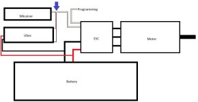
Please let me know if this diagram is accurate.

disconnect the positive line from the ESC to the receiver and in place of that connect the positive wire from the Ubec.
Untitled.jpg
 
The UBEC will need to come through your battery discharge wires to power your RC receiver/ Wiiceiver.

If you are using an on/off switch. You want it at the end of the on/off switch before the ESC. I simply just solder it to the end of the wires. Usually on the side of the bullet connector is the easiest and heatshrink over it.

You would then plug in the UBEC wire to one of the 3 pin ports either on the Wiiceiver and/or on a typical RC receiver.

To program the 12S ESC, you should of also bought the LCD Programmer. Plug in the UBEC on the first 3 pin port on the back of the LCD programmer. Plug the ESC Signal wire on the 3 pin port towards the center of the device. Power up your board and the lights on the LCD Programmer should come on and you can program the ESC.

Let me know if you need photos or videos on how to actually program it and I can whip some up for you.
 
Just a side note, a couple simple visual wiring diagrams like the one above, in a couple common configurations, would go a long way as stickies for the forum. I know to most of you it's too simple and "no duh" to bother with, but I think it would be a helpful visualization. I would make them, but I'd need some editorial input.
 
Of course theres lots of generic diagrams on Google to adapt from. Youre probably pretty busy torque--I'd do it, if I was a little more experienced. You can send me rough sketches, I can make basic illustrator diagrams. Anyways, sorry for the hijack.

Maybe this will help with original question:
 

Attachments

  • ubec-pro-wiring-diagram.png
    ubec-pro-wiring-diagram.png
    28.4 KB · Views: 943
Hello,

Since this thread already exists, I did not create a new one, I would like to know if I connected and soldered the wires correctly. I am using a FVT 12S opto ESC and UBEC, tried to follow the diagram but I am not sure if I did all correctly.

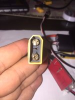
After I finished the soldering I wanted to try connecting to the motors to make sure it would work, I connected everything except the batteries which I connected last and when I did there was a HUGE spark and both the male and female connectors have now one side totally melted.

Assuming the wiring is correct (which please let me know if it is), would I be able to avoid the spark with the anti spark XT90 loop?

Thanks
 

Attachments

  • image.jpeg
    image.jpeg
    42.1 KB · Views: 1,568
  • image.jpeg
    image.jpeg
    44.4 KB · Views: 1,568
Thanks Okp, that really helped I was afraid to plug those battery again but the antispark loop did the trick.

Another thing, I noticed is that the BEC gets really hot after I plugged, turned the whole thing on and tested on my desk, is it normal?
 
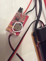
hi, I tried with another UBEC but it still gets hot after a few minutes. The component I circled in white is the one starting getting hot and after a while the whole unit gets hot. I have been told it is not normal for this to happen, anyone has any idea what I did wrong there?
 

Attachments

  • image.jpeg
    image.jpeg
    99.1 KB · Views: 1,528
I would expect if anything, it'd be the voltage regulator getting hot - especially at 12S, as it has to drop a larger voltage. That said I don't have any direct experience with the ubec, and I can't find any documentation on what that component you have circled is. Are the people who said it's atypical for it to get hot running at 12S?
 
Back
Top