Hi,
I'm working on a electric project and I just needed some help. I'm using a Kelly Controller KDZ48401 with an ME0909.
ME0909 is 48V, 100A cont and 300A for 30 seconds.
We have decided we will use two batteries - a 48V main one and a 18V to power just the controller (controller takes anything from 18->60V, only 150mA). My issue is that my circuit diagram is quite different to what Kelly Controller's example one is
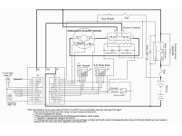
Their Example:

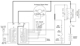
My one:
Solution 1: 48V Main Battery -> 325A Fuse (or 400A) -> Controller B+. Controller M+ -> ME0909 motor
18V Secondary -> 1A Fuse -> Key Switch -> Toggle Switch(behind brake) -> Controller PWR
Solution 2: 48V Main Battery -> 325A Fuse (or 400A) -> 2x 48VDC 250A circuit breakers in parallel ->Controller B+. Controller M+ -> ME0909 motor
18V Secondary -> 1A Fuse -> Key Switch -> Toggle Switch(behind brake) -> Controller PWR
Keep in mind I'm using 2/0 AWG wire everywhere
Q1: Do I need the circuit breakers in Solution 2 or will 1 work.
Q2: Will a 400A fuse be fine? (It's cheaper than the 325A)
Q3: Why does their diagram have this contactor and so many diodes. (Keep in mind, I don't want any reversing)
Ultimately, is my solution okay?
I'm working on a electric project and I just needed some help. I'm using a Kelly Controller KDZ48401 with an ME0909.
ME0909 is 48V, 100A cont and 300A for 30 seconds.
We have decided we will use two batteries - a 48V main one and a 18V to power just the controller (controller takes anything from 18->60V, only 150mA). My issue is that my circuit diagram is quite different to what Kelly Controller's example one is
Their Example:
My one:
Solution 1: 48V Main Battery -> 325A Fuse (or 400A) -> Controller B+. Controller M+ -> ME0909 motor
18V Secondary -> 1A Fuse -> Key Switch -> Toggle Switch(behind brake) -> Controller PWR
Solution 2: 48V Main Battery -> 325A Fuse (or 400A) -> 2x 48VDC 250A circuit breakers in parallel ->Controller B+. Controller M+ -> ME0909 motor
18V Secondary -> 1A Fuse -> Key Switch -> Toggle Switch(behind brake) -> Controller PWR
Keep in mind I'm using 2/0 AWG wire everywhere
Q1: Do I need the circuit breakers in Solution 2 or will 1 work.
Q2: Will a 400A fuse be fine? (It's cheaper than the 325A)
Q3: Why does their diagram have this contactor and so many diodes. (Keep in mind, I don't want any reversing)
Ultimately, is my solution okay?
")