Would it work to have 2 switches in my CA for if I see Cops?

Jazzjerry

1 mW
Joined
Jan 14, 2010
Messages
16
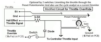
I have a cycle analyst and would like to use its th pad connected to my throttle signal to use it for economy sttings and current draw settings etc.

I also have the legal isue of speed in the Netherlands. So I would like to use a Preset Potentiometer that will reduce my speed with a preset speed of lets say the legal 25kph.

So this is switch 1 mounted on the cycle analyst. = Switch for a quick legal fix!

The other switch would be used to drive on an economical way using the limmiting function of the cycle analyst not just for speed limmiting but for current limmiting.

So both switches off = Full speed no limmiting
Just Switch 1 on Cycle analyst will follow my preset current limmiting
Just switch 2 on The potentiometer makes my speed go down to the preset.
Both switches on Both systems do their work.

My main questions are.....

1-Would this work?

2-Do I need another Diode after the preset potentiometer switch?


Hope someone knows more about it.
 
I am a noob ... I know but please think with me......

I made another drawing with a 3 pin pot meter maybe that one is better,,,,,,,

Please help the noob. I did not study electronics and would love to learn.
 

Attachments

  • CAmoddedrestrictor5.jpg
    CAmoddedrestrictor5.jpg
    29.3 KB · Views: 2,102
Jazzjerry said:
I also have the legal isue of speed in the Netherlands. So I would like to use a Preset Potentiometer that will reduce my speed with a preset speed of lets say the legal 25kph.

I don't know if the Netherlands are anything like the US, but if they are - cops just don't care.

1-Would this work?

Probably. But why not just use the Cycle Analyst's on-the-fly speed limit? You can use a switch and a potentiometer. See page 19 of the manual; just add a switch on the + side of the pot.
 
I would also like to use the limmiting function of the Cycle analyst in sence of current limmiting. To have a choice to drive more economical with the help of this function.

When I use the Cyce analyst for this reason, I cant use it for speed related limmiting. So I thought I would implement this option by adding the pot meter. So now I have 2 switches 1 is cops (In Holland they do care) and the other one is whatever I set the cycle analyst up for.

It would be nice to be able to limmit speed as fast as possible and not by ....... eHhhhhh wait a minute police officer, I have to put some new settings in before you can try my bike to see if it runs to fast....!
So I want to flip a switch and be sorted......

The pot meter will be preset for my max Kph and shrinkwrapped just for the sole purpose of police problems in the rear view mirror.

Both switches will be stealth in the form of mini switches under the CA.

Hope this makes sence.

But what do you think of this drawing would it work?

Best Regards,

Jeroen Compagne

The Netherlands

http://www.beeldhout.nl
 
To explain why the cops in Holland care....

In Holland when you turn 16 you are able to drive a moped.

Mopeds in Holland are only alowed to go 45 Kph and have a cilinder measurement of 49,9 cc's (metric system)
When you are 18 you are alowed to get your motorbike, or car drivinglicense.

When these rules where implemented , soon a lot of gearheads started tuning and modifying their mopeds to go faster and to look cool.
This has turned into a real subculture with legal and illegal races etc. The cops however adjusted quickly and started to hunt these moped anarchists. This
made them build al sorts of tools to get the moped anarchists of the road. So they have screanings every now and again with mobile 2 wheeler dyno units in every city. Everybody
driving motorised transport gets stopped and screaned every now and again. Since mopeds drive on bikelanes, cyclists are going to encounter these cops as well.

I know from 1 dutch e-friend that he has been stopped 2 times.Got a lot of crap because his pedelic sensr was not working propperly....<<<!!!
 
Anybody tried this before?

Hmmm........

Wish I would get some input that would help me feel safe to try this.
 
Jazzjerry said:
Anybody tried this before?

Wish I would get some input that would help me feel safe to try this.

It's an interesting approach and yes it will work. Using a potentiometer to simply limit the full scale throttle voltage and hence reduce the top speed to 25 kph is OK if this is something you will just do on occasion to show legality. But it means if it is scaled to 25 kph on the flats, you will go much slower than this on the uphills even though the system could otherwise have enough power to go uphill still at 25 kph.

If you wanted the 'economy' mode to just be a fixed current limit that you don't all the time need to readjust, then what I would do is the following:

Program the CA to have your desired economy current limit set (say 10 amps). Then program the speed limit to be something like 50 kph. In the setup menu, make it so that the Auxiliary Input voltage controls the speed limit functionality, and hook up the Vin pad with a voltage divider so that when you close a switch (Switch #1), Vin is at 2.5V, but when the switch is open then it is at the full 5V. Then put a 2nd switch (Switch #2) in series with the throttle over-ride line so that when this switch is open, then there is no speed or current limiting possible because the circuit isn't completed.

Then, with both switches open, you will have unlimited power. If you close switch #2, then you will have economy mode (10 amps but no speed limit). If you then also close switch #1, you will have the speed limit kick in a 25 kph as well.

-Justin
 
The way I understand you this means, I have to have both switches closed to be legal (in dutch country).

What makes your sugestion a better option compared to the option I gave in my schematic drawing? I have the Idear mine is either speed quick limmit or Current limmit (economy mode) without speed limmit.
Or would these 2 options start to resonate when at high speed and both engaged?

Just trying to bend my mind around this one.

P.S. I have no electronics skills. I am an artist (woodcarver) http://www.beeldhout.nl

Just so I understand what you mean, I made another drawing the way I think you suggest to build it.

Like I said before, I have no knowledge about electronics other then simple primary school education. After that I started studying Forrestry and Nature management. (I'm scared I am making big mistakes around you whizkids). But I dont mind people laughing about me though......
 

Attachments

  • CAmoddedrestrictor6a.jpg
    CAmoddedrestrictor6a.jpg
    29.3 KB · Views: 1,789
justin_le is your man Jerry, what ever he says as hes the one that designed and made the CA in the first place :)

Pitty about the moped brigade spoiling it for others, that two wheel dyno sounds like a
right bitch of an idea, hope that never happens in Australia or im screwed LoL...

KiM
 
Some of my controlles have a jumper wire that makes em euro legal when the wires are connected. A controller like that could just have a switch put on that jumper wire, and tell the cop it's the on off switch. So you flip the switch and presto your bike won't go faster than 20kph.
 
That would be nice,

But my controller does not. Wish they had this implemented would be a lot easyer.

But Trying to fix this myself is fun too. And teaches me a lot about EV technology.

Regards,

JJ :wink:
 
Jazz, you need you switch go work either way for seeing cops. ie One way makes it street legal, and the other setting is for out running them.
 
Jazzjerry said:
The way I understand you this means, I have to have both switches closed to be legal (in dutch country).

What makes your sugestion a better option compared to the option I gave in my schematic drawing?

Not much actually, the wiring seems more tidy in my head this way, but it has the downside that when you have the speed limit engaged there is also the current limit in place. It wouldn't let you do speed limit without a current limit. So in that sense I would say your original approach to simply limit the speed with a potentiometer on the throttle signal is a better idea.

Just so I understand what you mean, I made another drawing the way I think you suggest to build it.

Unlike the earlier drawings you made, this one is incorrect and wouldn't quite work. What I meant was to have the potentiometer wired between 5V, Gnd, and Vi (auxilliary voltage intput pad, not shown on your circuit). This is hooked up completely independent of the the Throttle Over-ride output circuitry (the output on the Th pad).

But for no electronics background, you are doing pretty good!

-Justin
 
Hello Justin,

Thanks again for the needed help.
I think I will go with my first drawing then. Its complicated for me already as it is. And I dont realy know that much about the Vi pad yet. Have to read up on that one first in your guides.

I will keep you guys posted on the results. Might not be for a while since my motor is in the bikeshop getting respoked.
This gives me some time to do this mod conversion though.

I must say I am very impressed by your cycle analyst. Also the way you produce it. Its a great addition to my EV pleasure.

Best Regards,

JJ
 
Hello Justin,

I like to know if this diagram is correct

Thanks
Black Arrow
 

Attachments

  • Overdrive.jpg
    Overdrive.jpg
    9.8 KB · Views: 666
BlackArrow said:
Hello Justin,

I like to know if this diagram is correct

This one was close, but you have it so that if switch #1 is open, then the input to Vi is floating and undefined. Instead, you want it so that if switch #1 is open, then the Vi pad is brought up to 5V. So just rearrange it slightly like so:

Double Limit CA Wiiring.jpg
 
Can these mods be used as well having a cruise control unit?
I have a Lyen edition 18 FET controller
CA direct plug in unit
PAS system
Cruise Control
Three way speed/power switch
72 v 20 Ah pack.

Or does having the 3 way switch and Cruise control negate the usefulness of these additions.
 
Back
Top