GUIDE: Modifying the DeWalt A123 charger to not be useless

Joined
Mar 30, 2007
Messages
645
Location
San Diego, CA
I'm an electronics newbie who tends to make fatal mistakes both real and theoretical, so I wanted the simplest method possible for adapting DeWalt 36V 2.3Ah battery packs for use in an e-bike.

The thing that is mandatory to change is the charging mechanism. Normally you have to take an individual battery and insert it directly into the charger; there's no cord. This is impossible to do when you have multiple batteries in series/parallel; you don't want to have to disconnect and remove each battery every time you need to recharge your e-bike.

There are three solutions:

1) Remove the BMS from each battery and attach one BMS to the charger, then use your own connectors to connect the BMS back to the battery for charging.
The advantage of this is you have full control over the connectors used, but the disadvantages are that you'd have to modify every single battery you use and this is pretty time-consuming. Besides, there would be 15 wires you'd need to connect, and wiring up a 15-pin connector for every battery would not be enjoyable.

2) Remove the connector from the charger and plug it into a battery basically forever, using your own connectors to connect that back to the charger.
This requires no modifications at all to the batteries, but you would need one charger for every battery to make it practical.

3) Remove the connector from the charger and extend the wires that go from the charger to it.
This is the solution I've chosen and will be detailing here. It's very easy to do and requires no modifications to the batteries themselves. The disadvantage compared to option #2 is that this connector still has to be plugged directly into the batteries, so you would need to make sure every battery you use is easily accessible on your vehicle.

First we need to remove the yellow cover from the charger. It is easily removed by unscrewing six screws on the bottom with a "tamper-proof" Torx T-15 bit:
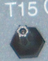
T15.jpg


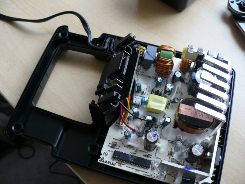
...not to be confused with the Torx T-10 that's needed for the battery's screws. Remove the cover and look at the connector in the middle. It turns out it's a completely separate piece of plastic that isn't even held down at all anymore! Here it is slightly lifted up and at an angle (the wires are quite short so it can't be moved much):
ConnectorLoose.jpg


Cut those wires. There are eight. We'll be splicing wire inbetween so try to leave enough length on each side to make the task easy.
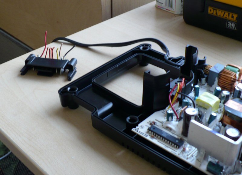
Removed.jpg


See? There's the connector removed from the charger. All I did was cut eight tiny wires and it's off.

The positive and ground wires appear to be 18-gauge, and the balancing signal wires are all around 22-gauge, possibly smaller. But I just used 20-gauge wire to connect everything. I cut all my wire to a generous five feet long so I could charge any battery anywhere on the bike without having to move the charger around. So... start splicing!

First wire soldered:
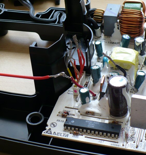
OneWireDone.jpg


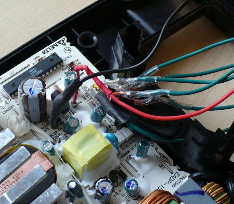
All eight soldered and wrapped:
HalfDone.jpg


Now if you didn't use a unique color for each wire then you should label them now so you can know which is which later. Then screw the yellow cover back on. There's room enough for the wires to escape through the bottom of the area where the connector used to be:
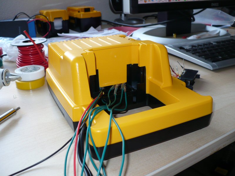
Reassembled.jpg


Now you should separate the wires into two groups and braid them around each other like a double-helix. This keeps them neat but flexible. You can also just use a wrap if you want, or tons of tape. Once that's done, attach the wires to the connector.

Because we're now exposing those contacts to physical stress and environmental hazards that it never was designed to deal with, I suggest using a hot-melt glue gun to drench the wires on both ends, both insulating them as well as making a good physical connection that can intercept stress otherwise placed on the solder joints themselves.

Now plug the connector into a battery and charge it! It goes like this (the entire black thing is the connector):
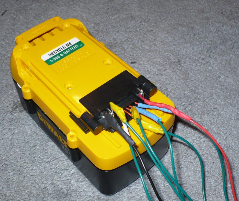
PluggedIn.jpg


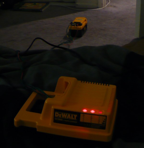
It's alive!

ItsAlive.jpg


Done! Not too bad. Getting additional chargers and making the same modifications should be a fairly quick procedure, but you only really need one anyway.

(edit: replaced broken image links)
 
Thanks for the great post. I'm in the stage where I'm considering batteries, and it was very helpful.
 
Yes, a helpful thread. Am I right in thinking that with all those wires on the charger board, the charger is responsible for balancing the batteries and not the battery pack's BMS? I'm a little confused as to what's the BMS you moved, and what's the charger.

If so, then it would seem the pack's BMS provides only a LVC and perhaps a current limiting function....interesting. Also, if this is the case, this charger mod should make it possible to charge and balance any 10-cell LiFePO4 pack with the Dewalt charger.

OneWireDone.jpg
 
I'm definitely not an expert, but I think the extra charger wires are only used to tell it when it should reduce power -- as cells reach full charge, less power overall needs to be sent to the pack. I recall reading something like that somewhere.

The charger does not balance the cells since there are only 5 balancing wires it has available to it, plus that PWM ground, regular ground, and positive. The real balancing is indeed done by the pack's BMS.

But as I mentioned in the original post, you can indeed remove the BMS from one pack and hook it up permanently to the charger, using it to charge any 10-cell A123 pack. The only reasons not to do this are that it's tedious and time-consuming work to do to every pack, and you'd have to deal with at least 13 wires, or 15 if you also want the temperature sensor to be hooked up.
 
That's a good ides to keep the BMS on the battery pack and to just extande the wire range from the charger to the battery pack as a charging harness.

I am working on that project to for my Dewalt pack too.

I already built the harness from my two dewalt charger to my ebike pack.

It is a 16 pin round amphenol round army style connector with"twist lock". I use a 10 ft cable of 16 conductor 18AWG that link two charger wire in the same cable. ALL INDEPENDENT WIRE .. it'S important! i have not joined ano of the neg or pos between chargers.. it's unusefull and a bit risky with my parallel/serie switch on the ebike.

I plan to put this double charger panel on the wall in my garage and leaving the cable free and ready to plug so i have simply to plug it on my ebike when i enter in my garage with the bike. This charger panel is smaller enough to allow me to put it in my rear bag even if i want to travel and having my charger with me. Each cahrger take 1h40 to charge each parallel pack

I also put a double diy voltage meter on me ebike dash to watch the two pack when wired in serie to avoid one to going under 25V. the only problem is that they are 5V supplyed and i needed to put a zenner + 5W resistor to lower the voltage and supply those. power draw 1.2W at 36V each.

I will post pics this week.
 
CGameProgrammer said:
I would be interested in how well your packs stay in balance since you're charging multiple cells in parallel.

If you are talking about charging, i can say that the BMS of the pack(I use one for 20cells 10s2p) simply need twice the time to fully balance the pack. +/-15mV

Doc
 
A spot on the DeWalts just showed up on Hackaday. Saw this .pdf linked and thought it could be useful to someone. I believe it shows a setup to charge multiple battery packs through the bms without internal modification. I'll need to read through it a few times to verify, but thought I'd post it for others to enjoy

http://www.neodymics.com/Images/V24ProtoSwitch070818E.pdf

edit: On second review it looks like they are still pulling the packs for charging in the original charger, but this is their method to link them for discharge. It's interesting they appear to be using the internal BMS and interfacing with the speed controller to set the max discharge. They also put an inductor in line with the controller. They say it helps smooth out the power spike from when they turn on the controller and all the capacitors want to charge up at once.
 
OMG !! :wink:

that's what we was waiting for a long time!

Many thanks

Doc
 
Turns out not to be a parallel charging setup as I had originally thought, so sorry this wound up in the wrong thread. Hopefully it proves useful all the same.

Running through the BMS, the neodymics setup isn't drawing more than about 12A from the pack at any time (2s2p), and I don't know if they confirmed the BMS will provide a cutout for a pack at low voltage or a cell that is below the recommended cutoff voltage. If it does that would be great.

Essentially this could be a warranty-proof way to use the packs. You are not discharging them more than spec, and are interfacing with them the same way a power tool does.
 
The thing is, the BMS uses small 18-gauge wire to interface with the cells, which has pretty high resistance even if not much current is being drawn from each battery. And you have to wire up so much just to get around the BMS' limitations...

If you do go that route, it's not necessary at all to use DeWalt connectors for discharging -- only the two main power terminals are used for discharge, and a simple spade/blade connector fits right in. I bought cheap spade connectors for 10-gauge wire at the local hardware store, but they were pretty small -- they fit, but somewhat loosely; I bet there's high resistance there. I still use them for testing the voltage of new packs before I open them up.
 
I think the small wires are only used for cell voltage monitoring and perhaps for cell balancing during charging, although that has yet to be difinitively shown. You still use spade terminals to draw your power. The inner spade terminal is the one protected/controlled by the BMS.

The only reason to do this is if it can be shown that the BMS has a reliable cutoff to protect the cells inside. If it doesn't, then clearly you just want to bypass the whole lot and ignore it.
 
No, there's no question that the 18-gauge wires deliver power from the A123 cells to the BMS and its spade connectors. The balancing wires are 22- or 24-gauge and those are totally different wires.

Among the A123 cells, there are no wires -- they're connected in series with tabs that can easily handle a lot of power.

As for your question, I have heard from others here that the BMS does not monitor discharge, and while I haven't verified it myself, it seems likely. I do remember a story of someone who had a battery shipped while connected to a DeWalt flashlight that was turned on, and it killed the battery because it severely overdischarged, since it was sitting in the package for a week while turned on.
 
On the Dewalt website, they clain that their 36V drill can deliver 750W.

Doing some math, 750W/ 33V=22.7A.

My opinion is that the small 18 gauge wire are short enough to drive at least this this 22A or baybe 30A.
the BMS use also a FDP038AN06A0 mosfet that is a

N-Channel PowerTrench MOSFET
60V, 80A, 3.8mohm.

The pack is balanced the next 15 minutes after the end of charging.

Doc
 
Sorry, I though you were referring to the little bms connector wires.

There are two ground paths to the cells. The "main ground" with the 15A fuse is the outside spade connection. The BMS does not provide any control over this path. The inner spade connection runs through the 60V 80A mosfet as pointed out by Doctorbass. This inner spade is not connected through the 15A fuse. It would be great if you could crank 22A through that mosfet with the right voltage dividers to the BMS pins. The neodymics diagram places an inductor in the line though to limit the inrush current, and they mention without it the BMS was shutting down the packs temporarily without the inductor to spread out that current spike.

It remains to be seen whether the BMS does anything useful during discharge.

Anyone have a pack they will test this on?
1. How much can you draw with the connections shown in the .PDF without the BMS stepping in and shutting down for overcurrent?
2. If wired up as shown, does the BMS actually intervene if you try to drain the cells beyond their discharge spec?

I nominate Doctorbass; he seems to have the cheapest source of packs, although the fact they are warranty returns doesn't exactly give me confidence the BMS is doing its job correctly.
 
I have a pack here on the bench i'm discharging right now. I'm almost sure that just connecting to the + or either of the - terminals WILL NOT offer low voltage cutout, that said, I am trying the inner - terminal again just to be sure.
Got no easy controlled way to test a 22A discharge unless I jerry rig it to the bike. I'll do it if I have time later, but this pack needs to come apart tonight to be rebuilt into a pack for someone else, so if I find any dodgy cells I will have my work cut out conditioning them all in time..
 
To pull power from the inner terminal is going to require wiring up the battery as shown in figure 1 of the following document

http://www.neodymics.com/Images/V24ProtoSwitch070818E.pdf

There should also be a lead from + to pin 9 (enable) to power the logic of the BMS (as shown in figure 2 of the .PDF)

Then you can draw through the inner spade terminal and test whether the BMS does anything useful during discharge and what the current limits are for this wiring configuration (up to 22A?)

WARNING: Doing any of the above is almost certain to result in releasing the magic smoke in the battery :D
 
Ok ok guy.. I understod...


I will do this famous test for you all.

I have 7 or 8 BMS that i have to blow for you 8)

For sure.. i will not blow all of them just for fun...!

I have a very big non inductive dummy load in my lab (a 3kW 0 to 10 ohm).. and....... a 0.25ohm 1.2kW..(60C at 36V ha haaa!)

I will try to enable it and see what i can get on the controlled output at different current.. and will finally TORTURE one just for you. :twisted:

I know teh circuit board have a 0.002ohm shunt to monitor the current... maeby i will bypass it even if it cut due to protection circuit Let's get REAL results!
What are your guess? will it blow at 20, 25, 30... 45??.... 50A??
let me know! i will try to give you the answer after the tests tonight!

Doc
 
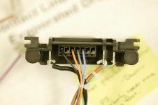
For additional info, you can see the pic of the pic of a connector that come with the 36V drill:


Also, about the flashlight, i know the circuit is similar, but it have an inductor on it.

Finally, already found an interesting disscussion on RCgroup forum about the BMS pins. here it is:

I have noticed that the top and bottom row of the 14 muti-pin connector seem to be the same top and bottom, so really only 7 connections besides the 3 main terminals. I can get the FET to turn on by pulling the center multi-pin to the positive side of the battery, but only with no load across the positive and FET output terminal. With a 470 ohm resistor across the positive to FET output, I get a short series of pulses across the load and then nothing untill I reset the process. I'm wondering if the input requires some type of pulse width control? Or it could just need a combination of control pins connected. I suppose the wise move would be to get a charger and drill, and then scope the logic on the multi-pin while in all modes of operation.

Kevin


and about the drill:
The circuit board in the impact wrench shorts two pins together, supplying power to the battery module. It also includes a resistor divider to apply voltage to a different pin, presumably indicating the presence of a tool (and perhaps even identifying the tool as well). If the signal connector pins are labeled with pin 1 next to the positive spade connector, then pins 3 and 4 are shorted and 2/3 of that voltage is applied to pin 5.

The board otherwise contains a freewheeling diode to protect the battery from polarity reversal (during motor direction changes) and a pair of transient voltage suppressors on the motor leads. The common terminal for the TVS's goes to pin 1 on the connector. Data logging, maybe? There is a 40 amp automotive-style blade fuse on the power input as well.

Bryan


Doc
 

Attachments

  • 1C2T7862small.JPG
    1C2T7862small.JPG
    27.2 KB · Views: 14,803
Nobody on this end is going to try to force you into destroying your toys; I'm just encouraging you to play with them some more :)

All in the interest of SCIENCE!


I'm guessing the BMS shuts off at ~25-30A.

I am still skeptical about whether it provides a low voltage cutoff to protect the cells... I'd love to be proven wrong.

At least you know your little mad-scientist experiment won't harm the cells, you've proven them under far worse conditions.
 
I'm guessing the inductor on the flashlight is to clamp/spread out current spikes like the neodymics folks have on their e-bike system.

The drill is a somewhat inductive load anyway, so an additional inductor isn't needed.
 
I just built the circuit to activate the BMS with potentiometer instead of resistor differents value.

IT WORK!

I will post results tonight as promissed.

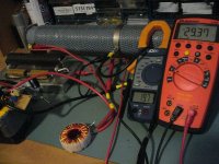
Here some pics of my circuit
(i use 3 x 10k pot + 1x 250uhenry inductor and a simple switch)

Doc
 
I started to test with a combinaison of load that give 1.5ohms load and I just got only 10volts when using the R valur of de desing in the PDF that are:
7.7K for the R2
8.5K for R3
and 1K for R4

I heard a low hf noise and the coil (a 250uH) created oscillation and the BMS cut after 5sec... I decided to bypass it and that solved the problem

I began to change value of these resistor that i replaced by 3 pot and got better results.
I got 29.37V at 19.7A that give 578W.

This time i heard no noise indicating me that probably the PWM reached the full duty cycle.

here are my resistor value for full PWM:

7.26K for the R2
7.28K for R3
and 4K for R4

Note that changing value of R4 did'nt change voltage at output.

I suspect that normally, the r valur that control the duty cycle should be a simple pot that replace the two resistor R2 and R3 that are in serie an dthat the pin 5 should be the middle connection of the voltage divider between pin 1 and 7... I supose...

Doc
 

Attachments

  • P1030028_800x600.jpg
    P1030028_800x600.jpg
    107.6 KB · Views: 14,724
Back
Top