Ktronik's "The Blinder" LED Tail Light Project

ambroseliao

100 kW
Joined
Apr 27, 2009
Messages
1,229
Location
Washington, DC, USA area
Hi Folks,

I was following this thread: http://www.endless-sphere.com/forums/viewtopic.php?f=3&t=12907 when Ktronik posted a note about his extremely bright tail light called "The Blinder." http://www.endless-sphere.com/forums/viewtopic.php?f=3&t=12907&start=30#p194219

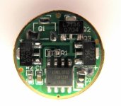
He posted the two components needed to build the light so I bought them! They are the 16 mode driver board: http://www.dealextreme.com/details.dx/sku.7612

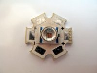
and the red Cree emitter: http://www.dealextreme.com/details.dx/sku.1776


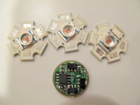
They've arrived and I've taken some photos of them:
IMG_0694.JPG
IMG_0700.JPG
IMG_0703.JPG

The driver board is very small. Smaller than a U.S. dime and the Cree emitters are about the size of a U.S. penny. Total cost so far is $14.58 USD. I plan on using 3 AAA or AA rechargeable batteries as the power source. These are easier for me to charge than the more powerful LiFePO4 batteries.

I plan on assembling these components into a tail light that I would be able to mount to my TF S-750 and have it be visible in three directions. One pointing backwards and the other two pointing left and right. I have a MagicShine P7 "900" lumen headlamp so the front should be covered. :D

First thing I'll need is a very small soldering iron since the soldering pads on the LED and driver boards are really tiny! Second, I'll need very thin insulated wire to connect these together.

More later,
Ambrose
 
Good deal!

Can't wait to see the finished product :mrgreen:

Hey.. still waiting on pics of your MagicShine headlamp via your blog..
Was it up to spec? Did you sear your retina's :shock:
 
Thanks for the photos. I'm trying to figure out how to bypass having to cycle through all those modes each time I turn on, then turn off, the driver board. It could get tiresome having to click my power button 15 times when I turn the tail light on.

I have a taillight now that has 5 different flashing settings, and even that one is sort of a hassle to turn on and off at times.
 
The Journey Guy said:
Thanks for the photos. I'm trying to figure out how to bypass having to cycle through all those modes each time I turn on, then turn off, the driver board. It could get tiresome having to click my power button 15 times when I turn the tail light on.

I have a taillight now that has 5 different flashing settings, and even that one is sort of a hassle to turn on and off at times.

Hey Nice one... :D

Better to use 4AAA/AA as you have a 500mA-1000mA drain from battery pack.. you would get a tiny voltage sag due to the drain on AAA, no probs for circuit @ 6v (4AAA/AA)

The Journey Guy

My driver had a 'memory' for the last mode used...reckon this one would have it as well... once set to the right mode, mine would turn on in 'last use mode' every time... no mode cycling other than the first setup for me

K
 
ktronik said:
The Journey Guy

My driver had 'memory' mode...reckon this one would have it as well... once set to the right mode, mine would turn on in 'last use mode' every time... no mode cycling other than the first setup for me

K

That's good news. When mine gets here, I'll do some bench tests to see if this driver has the same 'memory' mode.
 
I have some konions. All u have to buy is a single cell charger. Ive seen one konion cell dump 35A. So 1A should be no problem. A 18650 pack should be mated with those lights would be a wet dream. I have enough konion cells to make a 7.4v 9AH pack if you are intrested.
 
Ice is on to it...get a cheap 18650 from DX & cheap charger...but must be a 3.6v pack if using lithium as 7.2v is too high... as its a LDO type reg...

amc1.gif


P7-Multi-Drv01.gif

if just for the red flasher, just wire up the left driver on the first pic...same as pic for batt+ batt- LED+ LED-, but not the other connections to the other PCB...it is not used for the 3 LED flasher, but could be, if you wanted to drive more leds for signaling space ships or something, 6-10 LED would be ideal...hook them up the same way, all LEDs in parallel...
 
News flash:

Kaidomain (DX type place) have the PCB I have been using...looks like it anyway...

http://www.kaidomain.com/ProductDetails.aspx?ProductId=1677


They show the other DX driver you have, with this power input wiring..might be easier than the thin pad around the outside...

633788013663487726.JPG


A mate trouty, has done his this way...

a piece of round acrylic bar cut down the middle and sat over the leds would make it like a solid state thingy
McTroutlite006.jpg

a bit like this experiment I did last year the tape was just to stop the bar from falling out of the U channel
McTroutlite002.jpg

with a beam shot like this only in red
NEWMR16PROJECT055.jpg
 
ktronik said:
News flash:

Kaidomain (DX type place) have the PCB I have been using...looks like it anyway...

http://www.kaidomain.com/ProductDetails.aspx?ProductId=1677

OK, I'm going to show my ignorance here, and ask a question that has been on my mind.

Would it be possible to hook up the leds in parallel and run them straight from a power source, without a driver board?
I understand there would be no flashing, but if all I wanted was a constant light, could I do that without a driver?
 
The Journey Guy said:
ktronik said:
News flash:

Kaidomain (DX type place) have the PCB I have been using...looks like it anyway...

http://www.kaidomain.com/ProductDetails.aspx?ProductId=1677

OK, I'm going to show my ignorance here, and ask a question that has been on my mind.

Would it be possible to hook up the leds in parallel and run them straight from a power source, without a driver board?
I understand there would be no flashing, but if all I wanted was a constant light, could I do that without a driver?


LEDs need constant current, not constant voltage, as the LED warms it will want to drain more current (for same voltage), a CC source stops this from happening. if it was to happen the LED might go into 'thermal runaway' & die, So No, but Yes, if you are very careful to make sure gets no more than 3.6v....in this case, where you are running each LED @ lower than 1000mA (in this case 3 share 1000ma) you could hook directly to 3.0v & you will still light the LEDs & have not much chance of killing them...

so do a test...hook up 3 parallel LEDs to a 3.0v batt & check the current drain for a second, depending on the Vf of the LED you may get your 1000ma...if not go higher volts & use a resistor to drop the current to find the sweet spot for you LEDs... this is called 'direct driving' w ballast resistor...you will find a resistor calc on the net to help with resistor value...but really Direct Drive is NOT the go...for the sake of a $3 driver & 10min work...

K
 
I see your point now that you have explained it to me. Yes, a $3 investment is certainly the way to go with this project. I appreciate you taking the time and effort to enlighten me on this!
 
Hi Ktronik,

Any idea what gauge wire go into those tiny little holes on the driver board? Also, what gauge wire works well to wire to the LEDs?

Thanks,
Ambrose
 
ambroseliao said:
Hi Ktronik,

Any idea what gauge wire go into those tiny little holes on the driver board? Also, what gauge wire works well to wire to the LEDs?

Thanks,
Ambrose

No holes on PCB are used for our wiring, its all SMT stuff, so you only get a pad to work with...24AWG is more than fine for such a low current rating...& is handy for such small pads & tracks...

K
 
Thanks for that info! I was wondering how I was going to find wire small enough to fit through those tiny holes! :)

Ambrose
 
ambroseliao said:
Thanks for that info! I was wondering how I was going to find wire small enough to fit through those tiny holes! :)

Ambrose

Hey Ambrose, what soldering iron are you going to use for this small stuff? Right now, all I have is a 60w iron, and I know that's too big for this
detailed job.
 
I have a small soldering iron that I think is 15 watts that I got many years ago. I think they sell similar ones at Radio Shack. I don't know if the tip is small enough, but that's easy enough to replace with a very small pointed tip.

Ambrose
 
The Journey Guy said:
I'll take a trip to the local RS to see what they have. They probably have small tips available too, and if not, I'll just grind one down some.

Err, grinding down will kill the tip & it won't take solder again...must have a layer on the out side of the tip something that makes the solder take to the tip...been there done that, no wokie...

DX has a great soldering iron, temp control, small SMT type tip...

K
 
This might be the one:

http://www.dealextreme.com/details.dx/sku.1874

It's got a small handled soldering iron which normally indicates a small tipped iron.

Ambrose
 
ambroseliao said:
This might be the one:

http://www.dealextreme.com/details.dx/sku.1874

It's got a small handled soldering iron which normally indicates a small tipped iron.

Ambrose


Thanks ambroseliao, that's it, for the money you can't go wrong...365degC is a good temp for quick work without burning the tracks...reading the user posts on it, you may need a quick mod to move a wire away from the heating element...

I don't have one of these, but may be OK as its a copy of a good one...

K
 
Looking forward to some beam shots.
Wondering why you chose to do red LED's instead of white with a red lens?
I may just give this a go myself but I was thinking about using one of the "900" lumen P7's for the tail :twisted:

I have one of those "900" Lumen LED's in a flashlight up front... dude.... in high mode it lights up the trail like the ghetto bird!
Insane LED's. I suspect you get about 2hrs from the quad 18650 since I get 1 hour with two of them and I have measure the LED to burn 12W when it sees 1.5A from 8V

You may like this ->

I have an $8 switching power supply that puts out 9V 2A.... it is as small as a large pack of gum and it can be connected directly to the main battery to run the flashlight indefinitely.
For a big pack (say 24S) that is 12W / 88V = 137mA draw. Double that for losses and it only takes a quarter of an amp to run insane lights.

-methods
 
Methods,

Where can you get that $8 9V 2A switching power supply? That sounds great for a way to eliminate another battery to charge just for the lights.

Thanks,
Ambrose
 
methods said:
Wondering why you chose to do red LED's instead of white with a red lens?
Don't know about him, but I'd do it because it's much more efficient to use red LEDs for this. All the power you are outputting as light is being used, instead of perhaps a third or less of it. :)

I'd guess it's the same reason many if not most cars that use LED marker, signal, and taillighting use clear lenses over those areas, only using colored lenses for the reflectors.

And I'd also like to know where to get that power converter. :)

I've been looking at adapting the Roman Black designs for this purpose, but haven't gotten around to it yet.
 
Back
Top