Thanks everyone ... great thread. You inspired me to add lights to my ebike (and a horn and GPS tracking too ... why not!) Attached is my wiring diagram which may help others.
View attachment 4
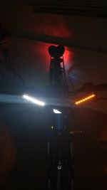
I got a harness extension cable for the BBSHD and spliced into the red and white wires for the brake signal. I just have a standard brake light (not flashing). I used a 3-position switch on the output of the running light strobe so I can set the running lights to ON, OFF, or STROBE.
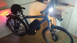
I found some "switchback dual color" LED strips that I mounted on my handlebar brake reservoirs. When the turn signals are activated, the white LEDs automatically turn off so you can see the amber LED turn signals more clearly. (See pic). When the turn signals are deactivated, the white LED running lights turn back on.
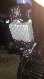
I housed everything in a large controller box and ran all the wiring to it using 22ga 5-conductor wires. All the wires were wrapped in split braided sleeve to make it not so ugly.
Not shown in the wiring diagram are some amber LEDs that I mounted to the controller box for some side marker lights. I just wired them to the running light circuit.
For the GPS tracking, it's just an old cell phone with a prepaid plan for about $10 every 3 months. Using one of a few different car alarm apps, it can text another phone the GPS location upon request.

")